background image

Page 50

www.yerf-dog.com

For questions in USA, 888-926-6554

Manual# 06367

Yerf-Dog Retriever CUV Owners Manual

Model# 34851 • Revision C - 2/05

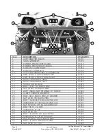
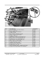
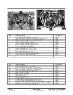
CARGO BED REPLACEMENT PARTS FOR MODEL 34851

Item
1
2
3
4
5
6
7
9
10
11
13
14
15
16
18
19
20
21
22
23
24
25
27
28
29
30
31

DESCRIPTION

      FFA PART #

Handle;Bed;Latch;Side; Roto

06423

Prop Rod;CUV 

06141

Plate; Latch; Tailgate; CUV 

06142

Spring;2.875 x .065 Dia;Latch;CUV 

06143

Spring;2.5 x .0638 Dia;Latch;CUV 

06144

Insert;3/8" Internal Thread 

06145

Insert;3/8" Non Internal Thread 

06146

Plate;Pivot;Slider;CUV 

06148

Bushing;Slotted;2";Yellow Zinc 

06149

Rod;Tailgate 44” Attachment;CUV 

06368

Lanyard; Spring Pin; Combo 

06152

Bolt 3/8" x 1" ;Hex;Blk Zinc;Nylon Patch 

06153

Bolt; Hex; 3/8" x 4-3/4" 

06427

Bolt;1/4"x2-1/2"";Hex;Zinc 

06155

Bolt;3/8"x6-1/2";Hex;Zinc 

06157

Nut;3/8";Nylock 

05196

Nut;1/4";Nylock 

001203P

Dump Bed;Plastic;CUV 

06158

Tailgate;Plastic;CUV 

06159

Bed; Dump; Undercarriage

06422

Rivet;Push-In; 1-1/8 

06363

Bolt; Butt Soc; 3/8 x 2; Black Zinc w/Sems Washer

06457

Bolt;1/4"x1-1/2;Hex;Zinc 

06178

Bolt; Carriage; 3/8 x 2; Black Zinc w/Sems Washer

06458

Pivot; Latch Handle; CUV

06424

Washer; Lock; 3/8”; CZ

001664P

Nut; Hex; 3/8-16; CZ

001215P

Summary of Contents for Retriever 4x2

Page 1: ...Page 1 www yerf dog com For questions in USA 888 926 6554 Yerf Dog Retriever CUV Owners Manual Model 34851 Revision C 2 05 Manual 06367...

Page 2: ...ranslated to another language without the written consent of Yerf Dog The information contained in this document is subject to change without notice Photos may vary slightly because of design improvem...

Page 3: ...tep of the operating instructions in this manual If you provide this unit for use by others we encourage you to recommend the reading and strict adherence to the recommendations in this manual If for...

Page 4: ...tial operation of your unit you may have difficulty shifting into forward and reverse If you have this difficulty slightly rock your unit from side to side to allow the gears in the transmission to al...

Page 5: ...ule 23 Periodic Lubrication Schedule 25 Engine Oil 26 Engine Oil Change 27 Transmission Oil Change 27 Fueling Instructions 28 Battery 28 Spark Plug 30 Drive Chain 30 Suspension 30 Cleaning the Vehicle...

Page 6: ...unsafe practice that could result in minor personal injury or product or property damage A WARNING indicates an immediate hazard that could result in severe personal injury or death INTRODUCTORY SAFET...

Page 7: ...pages 8 9 Remove all cargo before raising the cargo bed or servicing the vehicle Do not close cargo bed until all persons are clear of cargo bed area Keep hands clear of all crush areas Do not drop c...

Page 8: ...el level T O S TA R T E N G I N E Place shift lever in N Neutral position Depress brake pedal Turn key switch to START position and release T O O P E R AT E V E H I C L E Make sure wheels are turned i...

Page 9: ...OR DEATH NO SMOKING SPARKS OR OPEN FLAME STOP ENGINE ALLOW TO COOL BEFORE REFUELING DO NOT FILL TANK ABOVE THE BOTTOM EDGE OF THE SIDE FILL ACCESS Vehicle rated capacity 765 lbs on level surface only...

Page 10: ...eft side of the engine crankcase The Retriever vehicle Serial Number and Engine Serial Number are important for model identification when registering your vehicle obtaining insurance or whenever repla...

Page 11: ...n the dash Figure 3 The lever has three distinct positions F FORWARD N NEUTRAL and R REVERSE Pull handle downward F to operate the vehicle in the forward direction or upward R to operate the vehicle i...

Page 12: ...d return before starting the engine Check occasionally during driving The normal free play of the accelerator pedal is 1 8 3 8 inch 5 mm 10 mm To measure free play measure the rotation of the accelera...

Page 13: ...ontrol is located on the dash panel to the left of the steering column Figure 8 Pull the headlight control knob out to turn headlights on and push the knob in to turn headlights off We recommend headl...

Page 14: ...NG THIS VEHICLE That s why you should read and be sure you understand all the warnings and instructions in this manual and in the decals on the vehicle itself before operating it CAUTION A CAUTION ind...

Page 15: ...verse handle in FORWARD the vehicle should accelerate smoothly to full speed as the accelerator pedal is depressed When the pedal is released it should return to the original position and the engine s...

Page 16: ...ns Use brakes to reduce speed when coasting downhill Never attempt jumps Wet brakes have reduced stopping ability Test your brakes after leaving water If necessary apply them several times to let fric...

Page 17: ...engage the parking brake and the vehicle will start to move As the accelerator is depressed speed will increase until full speed is reached See following WARNING Operator must always control vehicle s...

Page 18: ...lace the Forward Reverse handle in the NEUTRAL position and remove the key 3 If parking vehicle on unlevel ground we recommend using wheel chocks for added safety Read DANGER and WARNING on page 7 The...

Page 19: ...ring and braking of the vehicle To help prevent cargo from shifting and possibly injuring a passenger or affecting the vehicle s handling make sure cargo is well secured Avoid top heavy loads The cent...

Page 20: ...d when towing Do not allow riders in or on whatever is being towed towed vehicle trailer etc Total vehicle capacity including the vehicle load rating and the gross weight of the vehicle or trailer bei...

Page 21: ...the trailer with the Forward Reverse handle in NEUTRAL the key switch OFF and the parking brake firmly engaged Because of the added length of the trailer use caution when making turns Do not transpor...

Page 22: ...t battery cables positive cable first 3 Place the Forward Reverse handle in the NEUTRAL position and engage parking brake Crank the engine until fuel is pumped into the carburetor and fuel lines and t...

Page 23: ...vehicle powertrain or under the cargo bed when it is loaded and or if the parking brake is disengaged Hot Do not attempt to service hot engine or exhaust system Failure to heed this warning could resu...

Page 24: ...ecessary See Vehicle Specifications on page 39 Wash engine compartment and underside of vehicle Do not wash engine when hot Clean terminals and wash dirt from casing check electrolyte level See Batter...

Page 25: ...ITEM Engine Oil Transmission Oil Drive Chain Front A Arm LUBRICATION RECOMMENDATION METHOD SF SG SAE 15W 40 SAE 85W 140 Chain Lube or 85W 140 Grease See page 27 Change every 6 months or every 100 hour...

Page 26: ...as indicated by the Oil Viscosity Recommendation Chart Figure 12 See following NOTE NOTE Using multi grade oils 5W 20 1OW 30 and 1OW 40 will increase oil consumption Check oil level more frequently wh...

Page 27: ...nit for at least five 5 minutes or until warm Turn Engine OFF and remove the key 2 Place suitable container for draining oil beneath the engine 3 Remove the engine drain plug oil filter cap spring and...

Page 28: ...king on or near batteries Tools wires and metal objects can cause sparks when shorted across a battery Follow all instructions carefully when working with batteries Charge battery in a well ventilated...

Page 29: ...components from box and place battery on a level surface 2 Fill battery with electrolyte and charge as outlined in the motorcycle battery dry charged instructions Use caution when handling electrolyte...

Page 30: ...e front right and left side suspension can be adjusted to various pre load positions so they can be matched to load and driving conditions www yerf dog com For questions in USA 888 926 6554 Retriever...

Page 31: ...attachment 1 hour STEERING COLUMN ASSEMBLY For shipping purposes the steering column is disconnected from the dash mount and folded down during shipping To reconnect the steering column lift it up an...

Page 32: ...cture to help illustrate and attach the 2 875 spring p n 06143 using bolt a 3 8 x 1 p n 06153 3 8 x 2 3 8 x 1 1 2 1 Your hardware bag should contain the following bed latch assembly components Pivot P...

Page 33: ...ports Fasten using 2 3 8 nylock nuts p n 001205P 10 While keeping the prop rod in the slide tray lower the dump bed enough to insert the end of the prop rod handle into the hole on the bottom of the d...

Page 34: ...6153 placing a 3 8 flat washer p n 001614P between the head of the bolt and the spring Thread the bolt into the insert closest to the rear of the dump bed 15 Attach the spring p n 06144 to the prop ro...

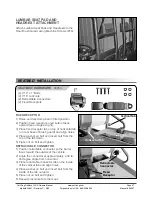
Page 35: ...t Washers 09 8 3 8 Lock Nuts 10 2 3 8 Studs LUMBAR SEAT PAD HEADREST HARDWARE 14 Machine Screws 06883 Insert all bolts and nuts before tightening The Brush Guard Components are not designed or intende...

Page 36: ...passenger side brush guards before attaching to unit BRUSH GUARD ATTACHMENT STEP 2 PASSENGER SIDE Attach passenger Side Brush Guard to the vehicle frame at rear using Bolts 07 Washers 08 and Nuts 09...

Page 37: ...image at right 3 Place fixed receptor tab on top of horizontal tab on rear base of brush guard and align holes 4 Place washer on bolt and insert bolt from the top of the tab down 5 Place nut on bolt...

Page 38: ...fuel The following information is provided to help you identify probable questions you may have about the operation of your Retriever vehicle See your Service Center with any additional questions you...

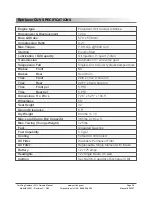
Page 39: ...Max Load Cargo Box Capacity Max Towing Tounge Weight Fuel Fuel Capability Cooling Oil Filter Air Filter Battery Headlights Ignition Forced Air Oil Cooled 4 Stroke 10 hp 57 4 x 57 8mm 9 2 1 7 0 ft lbs...

Page 40: ...FFA PART 04779 04780 04781 04782 04783 04784 04785 04786 04787 04788 04789 04790 04791 Retriever VEHICLE PARTS LIST Please use this Retriever vehicle parts list with illustrations to correctly identi...

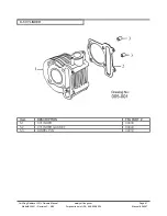
Page 41: ...com For questions in USA 888 926 6554 Yerf Dog Retriever CUV Owners Manual Model 34851 Revision C 2 05 Manual 06367 Item 5 1 5 2 5 3 D 5 CYLINDER DESCRIPTION CYLINDER CYLINDER GASKET DOWEL PIN FFA PA...

Page 42: ...1 6 2 6 3 6 3 1 6 3 2 6 3 3 6 3 4 6 4 6 5 6 6 6 7 6 8 6 9 6 10 6 11 6 11 1 6 11 2 6 12 6 12 1 6 13 6 14 6 15 DESCRIPTION RIGHT CRANKCASE OVER OIL SEAL GASKET R CRANKCASE COVER SCREEN OIL FILTER ASS Y...

Page 43: ...COVER L GASKET L COVER HEX FLANGE BOLT HEX FLANGE BOLT DOWEL PIN STRAP DUCT L CRANKCASE COVER BREATHER HOSE CLIP DUST PROOF RUBBER TAPPING SCREW FFA PART 04873 04874 04853 04817 04852 04875 04876 0487...

Page 44: ...MENT SEAL OIL CATCH SEAL OIL CLEANER COVER AIR CLEANER CASE CLEANER CASE CAP COVER OIL CATCH FILTER BREATHER FILTER OIL CATCH AIR CLEANER JOINT DUCT AIR CLEANER IN DUCT AIR CLEANER CASE SPRING IN DUCT...

Page 45: ...IPTION EXHAUST PIPE ASS Y EXHAUST PIPE GASKET EXHAUST PIPE NUT CAP HEX FLANGE BOLT CARBURETOR ASS Y CHOKE WIRE FUEL PUMP COMP SIDE OIL TUBE FUEL TUBE B FUEL TUBE C FUEL FILTER ASSY FUEL TUBE D CLIP CL...

Page 46: ...12 16 13 16 14 16 15 DESCRIPTION FRAME COMP RIGHT ENGINE BRACKET PLATE LEFT ENGINE BRACKET PLATE PROTECTION FRAME BOTTOM BOARD PAN PHILLIPS BOLT SPRING WASHER REAR ENGINE BRACKET PLATE HEX WASHER FAC...

Page 47: ...PRIVE CHAIN ASS Y CHAIN TENSIONER ASS Y CHAIN TENSIONER BRACKET PLASTIC ROLLER FIX SHAFT NEEDLE BEARING PLASTIC ROLLER PLAIN WASHER E RING NYLON INSERT LOCK NUT SPRING HEX FLANGE BOLT FFA PART 05100 0...

Page 48: ...13 21 13 1 21 14 21 15 DESCRIPTION MAIN WIRE COWL MAIN WIRE ENGINE FUSE IGNITION COIL ASS Y C D I UNIT ASS Y FIX RUBBER RECTIFIER REGULATOR STARTER RELAY ASSY HEX FLANGE NUT SERPATION HOUR METER ELEC...

Page 49: ...BLACK W HARDWARE 04140 SEAT BACK LEFT 05165 SEAT BACK RIGHT 05166 HEAD REST 2 IN BOX 05167 TIRE 22X11 8 2 PLY LEFT REAR 04667 NUT LUG M14 ZINC 04667 TIRE 22X11 8 2 PLY RIGHT REAR 04259 FENDER REAR BL...

Page 50: ...nsert 3 8 Non Internal Thread 06146 Plate Pivot Slider CUV 06148 Bushing Slotted 2 Yellow Zinc 06149 Rod Tailgate 44 Attachment CUV 06368 Lanyard Spring Pin Combo 06152 Bolt 3 8 x 1 Hex Blk Zinc Nylon...

Page 51: ...SEE PAGE 8 9 OF THIS MANUAL 04680 BUMPER RECESSED VIBRATION DAMPENER RUBBER 06172 SCREW 10 16 x 1 1 2 HEX HEAD 06177 BATTERY CUV 04677 MISCELLANEOUS PARTS FOR 34851 Item 1 2 3 DESCRIPTION FFA PART Dec...

Page 52: ...SY HOOD OLIVE DRAB 06365 STEERING WHEEL W COVER 04678 SHIFTER ASSY 04669 POWER PORT 04768 BOLT 10 24X3 4 TH BLACK ZINK CUV 04685 WASHER FLAT 3 16 BLACK ZINK CUV 05191 NUT NYLOCK 3 16 BLACK ZINK CUV 04...

Page 53: ...USHION 04139 BOLT 1 4 X 1 05320 SPACER RUBBER SEAT 04698 FUEL TANK ASSY 04141 CLAMP BAR FUEL TANK KIT BLACK 04142 BOLT 1 4 20X1 2 BLACK ZINC 05197 BATTERY MOUNT BRACKET 04704 BOLT 1 4 20X1 BLACK OXIDE...

Page 54: ...Y W HARDWARE 04129 TIRE 22X9 10 2 PLY FRONT LEFT 04666 TIRE 22X9 10 2 PLY FRONT RIGHT 04258 RACK VIB DAMPER RIGHT 04649 RACK VIB DAMPER LEFT 04650 SHOCK 800 LB LOAD 04676 BOLT 7 16X1 3 4 BLACK ZINC 04...

Page 55: ...04710 SPRING THROTTLE 04738 GROMMET U JOINT SHIFTER THROTTLE 04675 BOLT 10 24X1 1 2 TH BLACK ZINK CUV 05192 WASHER FLAT 3 16 BLACK ZINK CUV 05191 NUT NYLOCK 3 16 BLACK ZINK CUV 04684 BOLT 3 8 x2 1 2...

Page 56: ...ASSY WDMT MAIN FRAME BLACK CUV 04654 BUMPER RECESSED VIBRATION DAMPENER RUBBER 06172 SCREW 10 16 X 1 1 2 HEX HEAD 06177 3 5 4 6 7 8 9 10 12 11 12 11 13 14 Item 3 4 5 6 7 8 9 10 11 12 13 14 DESCRIPTIO...

Page 57: ...isted in your owner s manual Yerf Dog recommends that you retain all receipts covering maintenance of your small off road engine but Yerf Dog cannot deny warranty solely for lack of receipts or for yo...

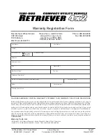
Page 58: ...ubb Ave West Point MS 39773 Phone 888 926 6554 Fax 662 495 5006 customerservice yerf dog com Please use this form to send us any comments on your experience with the Yerf Dog Retriever CUV We apprecia...

Page 59: ...onths Each warranty term begins on the date of product delivery to the purchaser WHAT IS NOT WARRANTED YERF DOG IS NOT RESPONSIBLE FOR THE FOLLOWING 1 Used Products 2 Any product that has been altered...

Reviews:

Related manuals for Retriever 4x2