background image

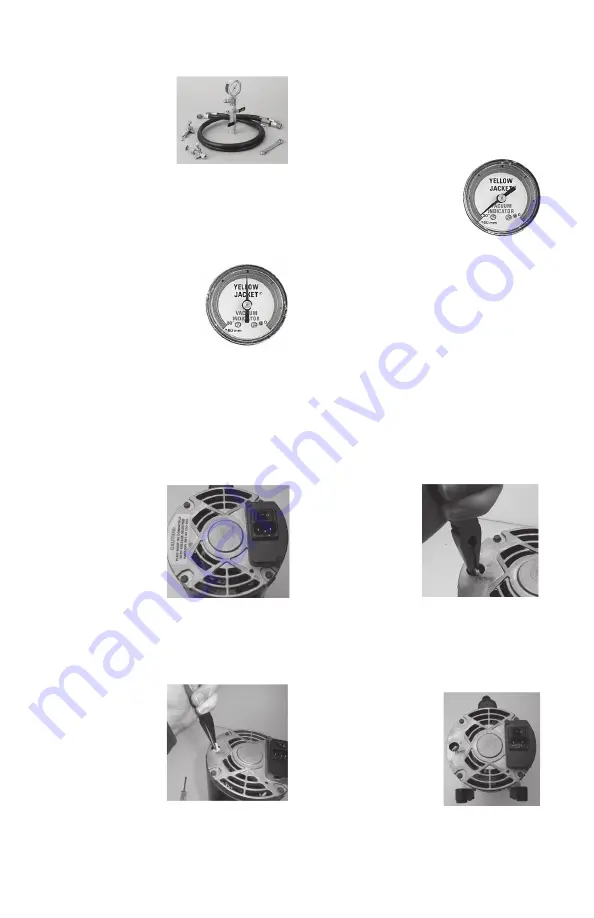
STEP 1

Disconnect the 

motor from the 

power supply 

and remove. 

Remove the yellow 

“CAUTION” sticker 

from the back of 
the motor.

STEP 2

Pull up on the white plastic “arrow” 

switch using needle-nosed pliers until 

the switch is loose 

inside the motor 

housing (it will not 

come completely 
out of the motor).

NOTE: Do not try to 
turn or rotate the 
switch until it has 
been pulled up and is loose.

If you think there is excessive mois-

ture, blow out the AC&R system with dry 

nitrogen wherever possible. This reduces 

the amount of contaminants that must 

be “pulled” into the pump and increases 

evacuation speed.
Use a nitrogen regulator 

valve with pressure limited 

to 150 psi and a frangible 

disc device set at 175 PSIG.
When the indicator reaches 

the 29-30” range, turn 

on the electronic micron 
gauge for more precise readings.

Oil Changes: CHANGE OIL AFTER EACH 

USAGE 

to protect pump components from 

contaminants pulled into pump during 

service. Place used oil in a sealable 

container and dispose properly in accor-

dance with local regulations.

STEP 3

Point the arrow 

toward the desired 

voltage setting and 

push the switch 

back down into the 

motor. The arrow on 

the switch should 

be sub-flush of the 

motor housing when correctly installed at 
the desired voltage.
HI = 230 VAC / 50 Hz

LO = 115 VAC / 60 Hz

STEP 4

Replace the yellow 

“CAUTION” sticker over 

the voltage selector 

switch. 
Ensure that the voltage 

setting corresponds 

with the power supply that the motor is 

plugged into.

6

8. Use a SuperEvac System I, II or III to 

decrease vacuum 

time by over 50%. 

These systems 

include a 2-valve 

vacuum manifold 

and two 3/8” 

vacuum hoses which can evacuate 

three times faster than a 1/4” hose.

9. Use a heat gun on the condenser and 

evaporator to speed the evacuation 

process.

Built-in Vacuum Gauge:


The built-in indicator 

gauge in your pump 

monitors evacuation 

progress down to the 

29-30” range. If the 

reading stays in the mid range, there is 

either high contamination or a large leak 

in the system. 

Gross Leak

Dual Voltage Motor Power Conversion (if applicable)

Turn on 

Electronic Gauge

*Warranty is void if the set vacuum pump voltage does not match the power supply.  Dual voltage

  motors are factory set to 230V/50Hz.

Summary of Contents for SuperEvac 9354 series

Page 1: ...SuperEvac Vacuum Pump Operation and Maintenance Manual Models 9354x 9356x 9358x 9359x...

Page 2: ...r s Bill of Lading and have shipper sign your statement Notify the carrier immediately of the damage to arrange inspection of the pump and packaging The CARRIER ALONE is responsible for handling and s...

Page 3: ...s that have been drawn into the pump as a result of evacuation 5 Opening the ballast allows fresh air to enter the cartridge and keep vapors from combining with the oil Vapors escape harmlessly throug...

Page 4: ...e similar to two single stage pumps connected together If air a non condensible remains in the system it collects on the high side reduc ing system efficiency This causes a rise in head pressure The d...

Page 5: ...shut off 7 Disconnect pump and put cap on intake to keep out contaminants 8 If an extension cord is needed refer to the below chart for proper sizing 6 Use the 4 in 1 Vacuum Charge Valve Core Tool Pa...

Page 6: ...in accor dance with local regulations STEP 3 Point the arrow toward the desired voltage setting and push the switch back down into the motor The arrow on the switch should be sub flush of the motor ho...

Page 7: ...o atmosphere and switch on pump run up to speed before connecting to system Four Most Common Comments on Pump Return Paperwork Your SuperEvac pump features a heavy duty high torque motor for cold weat...

Page 8: ...dropped Micron gauge malfunction Poor motor performance Dirty oil Air leaks System leaks Fitting sealant compound Call factory Verify with second gauge Repair or replace Flush 1 to 3 times Repair or...

Page 9: ...coupling Replace motor Tighten bolts Adjust replace coupling Pump Cartridge Dirt low improper oil Air leaks 1 Caps connections 2 Gaskets O rings 3 Fittings 4 System leak Flush and replace oil Tighten...

Page 10: ...2941 92941 92941 3 Oil fill cap and seal 93390 93390 93390 93390 4 Oil fill fitting 93391 93391 93391 93391 5 Pair of sight glass screws 92933 92933 92933 92933 6 Sight glass bezel 92934 92934 92934 9...

Page 11: ...Hz includes items 24 25 26a below 93505 93505 93505 93505 23b Export models 1 2 hp dual voltage 115V 60 Hz and 230V 50 Hz includes items 24 25 below 93513 93513 93513 93513 24 8 32 x 7 1 4 motor bolt...

Page 12: ...ely in need of normal field service maintenance such as changing oil or making minor adjustments In many instances the troubleshoot ing information in this manual can save you the time and effort of r...

Reviews: