yellow jacket 40812 User Manual Download Page 5

The illustration below shows three bars that indi-

cate a fresh or well-charged battery pack. When 

the battery weakens, the bars will disappear one-

by-one as the battery power decays. When one 

bar remains, the symbol will turn yellow. When all 

bars are gone, the batteries are nearly dead and 

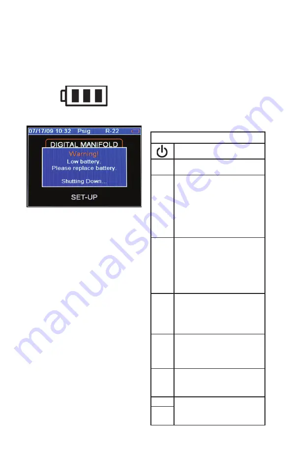
the symbol will turn red. The unit will briefly show 

a pop-up message just before the unit stores all 

data and then automatically shuts off.

Figure 2-2. Battery Power Symbol

Figure 2-3. Low Battery Pop-Up Message

Automatic Power Off

The instrument may automatically turn off after 

a period of time. The default is one hour. The 

user may select other settings from ten minutes 

to four hours from the Setup menu (see Chapter 

5). The user may also disable this feature. The 

Auto Power Off time limit is automatically disabled 

during data logging and is automatically restored 

once data logging has terminated.

Power Saving Mode

The display backlight will fade, darkening the 

display to save battery life if a key has not been 

pressed for a set period of time. While in Power 

Saving Mode, pressing any key turns the display 

backlight back to full brightness. Note that

backlighting is independent from the display 

brightness and contrast settings (see Chapter 5) 

which do not affect battery life. 

The Power Saving Mode is preset to 10 minutes. 

From the Setup menu (see Chapter 5), you can 

specify settings from 30 seconds to 60 minutes.

Low Battery Conditions

The unit will attempt to store all logged data if 

low battery power is detected. Once the data is 

stored, unit will turn off.

Maximizing Battery Life

Battery life decays fastest when the DIGITAL 

MANIFOLD display is selected, the vacuum sen-

sor is attached, and the backlight is on. Battery 

life during data logging is maximized by using 

high-performance batteries, detaching the vacuum 

sensor (if not in use), and a short Power Saving 

Mode time setting is selected.

Keyboard Keys

Note that pressing a key that has not been 

assigned to a function will result in three, short 

beeps.

Table 2-1. Key Functions

Power On/Off (see Chapter 2, Turn-

ing the Instrument On and Off).

Menu

Accesses menu of instrument     

functions.

Enter

Accepts selected functions and 

values.

This key will also toggle the instru-

ment data display modes. See 

Chapter 3.

During playback of logged data, 

toggles between point-by-point and 

page-by-page scrolling.

Clear

A single press clears the chart set 

point. (See Figure 3-1, item 11)

Press and hold to clear ‘Min.’ and 

‘Max.’ values. (See Figure 3-1,    

item 5)

Resets vacuum timer to 0:00:00. 

(See Chapter 3)

Hold

Freezes the data display at the 

moment the key is depressed when 

data is being displayed. A second 

key press will return the display to 

the normal, dynamic mode (not ac-

cessible during data logging).

Chart 

Time

Toggles time resolution to display 

more or less of the data acquisition 

event, enhancing a user’s ability to 

see significant events (not accessible 

during data logging).

Chart 

Pres-

sure

Toggles pressure resolution to fit 

analog pressure data within the 

display, enhancing a user’s ability to 

see significant events.

Up/Left Assists in selection of values and 

data points depending on the func-

tion feature involved (not accessible 

during data logging).

Down/

Right

5

Summary of Contents for 40812

Page 1: ...ached to the instrument YELLOW JACKET Refrigeration System Analyzer Users Manual UPC 40812 40813 and 40815 Versions 1 06 and higher 99 Washington Street Melrose MA 02176 Phone 781 665 1400 Toll Free 1...

Page 2: ...ions 15 Safety 15 Chapter Title Pg Features and Specifications 15 Instrumentation Specifications 16 Warranty Policy 16 Table of Contents List of Tables Table Title Pg 1 1 Safety Information 3 1 2 Symb...

Page 3: ...ced only by Ritchie Engineering Co or authorized service centers Do not use the instrument if it operates ab normally Protection may be impaired When in doubt have the instrument serviced Refer to war...

Page 4: ...page by page scrolling mode during data log playback Battery Battery connector orientation Chapter 2 Getting Acquainted Introduction This instrument will clearly and accurately report critical inform...

Page 5: ...is detected Once the data is stored unit will turn off Maximizing Battery Life Battery life decays fastest when the DIGITAL MANIFOLD display is selected the vacuum sen sor is attached and the backlig...

Page 6: ...Chart Display This display shows the P T Pressure Tempera ture chart for the refrigerant that is selected in the Set Up display Use the or keys to scroll through the chart Press the Menu key to exit...

Page 7: ...Transducer internal High Side Pressure Transducer internal Temperature Probes The system analyzer will display readings from any K type thermocouple probe with a miniature style connector see picture...

Page 8: ...erheat measurement the T1 probe should be mea suring the suction line temperature Temp 2 T2 The temperature indicated by the T2 thermocouple For proper subcool ing measurement the T2 probe should be m...

Page 9: ...High Side 3 When data recording is activated this indicator will gradually change from red to blue indicating the size of one page of data During playback it will help the user to decide whether to mo...

Page 10: ...for signs of oil before connecting the 69086 vacuum gauge sensor Keep the sensor vertical when possible Connect the gauge directly to the system away from the pump Isolate the pump from the system an...

Page 11: ...and reporting at a later time Figure 4 3 Data Log Files Erase File Use the arrow keys to highlight the data file to be erased Press clear to erase Erase All Files Press clear to erase all data files...

Page 12: ...ry default is MM DD YY Time and Date These settings are modified in a slightly different manner Selecting this setting for modification will open a pop up window Each component of the time and date va...

Page 13: ...as dish soap If the unit encounters enough exposure to liquid chemicals that the chemical wicks between the in strument boot and the case immediately remove the boot and clean the case as described ab...

Page 14: ...tem Analyzer Instrument Boot 40823 System Analyzer Battery Door 40824 System Analyzer Bumper Plugs Sensor Boots 40827 USB cable 69101 Vacuum Sensor Cord Assembly 69217 K Type Clamp Probe 10 ft Softwar...

Page 15: ...ls back to past readings Refrigerant Database 98 NIST refrigerant profiles included upgradeable Data Logging Adjustable time intervals from 0 1 to 10 seconds minimum of 24 hours at 1 0 second interval...

Page 16: ...Company Inc is guaranteed to be free from material and workmanship defects for a period of two years All other YELLOW JACKET products included in this package are guaranteed to be free from material a...

Reviews: