MyPBX U510 Installation Guide
http://www.yeastar.com 9/17
3.2.2 Connection of E1/T1/FXO/GSM/UMTS/BRI ports
MyPBX U510 supports various outside lines (e.g. E1/T1, FXO, GSM/UMTS, or BRI). Below are the connection
instructions of each kind of outside line taking the device installed with 1 E1/T1, 2 FXO ports, 2 GSM ports,
and 2 BRI ports as an example.
1.
Connection of E1/T1 port
The E1/T1 port could be connected to the E1 line or the E1 port of traditional PBX.
Note
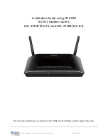
: the E1/T1 port of MyPBX U510 is RJ45 port, and the pins are defined as below table:
Item
Description
1
RX- Receive Data-
2
RX+ Receive Data+
3
Not used
4
TX- Transmit Data-
5
TX+ Transmit Data+
6
Not used
7
Not used
8
Not used
Note
: Please follow the below steps to make RJ45 cable to connect it to the E1 port.
Step 1
: Connect MyPBX U510 E1 port to the E1 line according to the line sequence of E1 port.
From the above table, we can see that the No.1 and No.2 pins of MyPBX U510 E1 port is for receiving
data (No.1 for receiving data -, No.2 for receiving data +), while No.4 and No.5 is for transmitting data
(No.4 is for transmitting data -, No.5 is for transmitting data +).
When connected to the E1 line, RX- of E1 port should be connected to TX- of E1 line; RX+ of E1 port
should be connected to TX+ of E1 line; TX- of E1 port should be connected to RX- of E1 line; TX+ of E1
port should be connected to RX+ of E1 line.
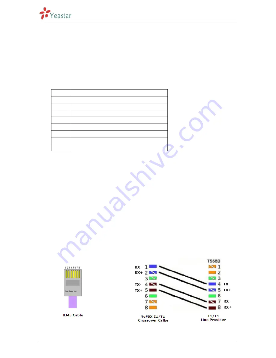
For example, the line sequence o f the E1 line (RJ45 port) provided by the telecom company is: No.4 for
TX-, No.5 for TX+, No.7 for RX- and No.8 for RX+ which apparently can
’
t correspond to that of MyPBX
U510 E1 port. So you need jumper, which could be depicted as below:
Figure 3-1 E1 Cable Cord Sequence