background image

Configuring System Settings


93 

2.


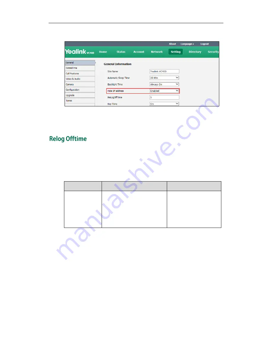
Select Enabled from the pull-down list of Hide IP Address. 


3.


Click Confirm to accept the change. 

The IP address is hidden from the status bar of the display device. 

The system will log out of the web user interface automatically after being inactive for a 
period of time (default: 5 minutes). You need to re-enter the user name and password to 
login. You can only configure the relog offtime via the web user interface. 

The relog offtime parameter is described below: 

Parameter 

Description 

Configuration Method 

ReLogOffTime 

Configures the inactive time (in 
minutes) before the system logs 
out the web user interface 
automatically. 

Default: 5 

Web User Interface 

To configure the relog offtime via the web user interface: 

1.


Click on Setting->General. 


Summary of Contents for VC Series

Page 1: ......

Page 2: ...THE PRODUCTS IN THIS GUIDE ARE SUBJECT TO CHANGE WITHOUT NOTICE ALL STATEMENTS INFORMATION AND RECOMMENDATIONS IN THIS GUIDE ARE BELIEVED TO BE ACCURATE AND PRESENTED WITHOUT WARRANTY OF ANY KIND EXPRESS OR IMPLIED USERS MUST TAKE FULL RESPONSIBILITY FOR THEIR USE OF PRODUCTS YEALINK NETWORK TECHNOLOGY CO LTD MAKES NO WARRANTY OF ANY KIND WITH REGARD TO THIS GUIDE INCLUDING BUT NOT LIMITED TO THE ...

Page 3: ...y to correct the interference by one or more of the following measures 1 Reorient or relocate the receiving antenna 2 Increase the separation between the equipment and receiver 3 Connect the equipment into an outlet on a circuit different from that to which the receiver is connected 4 Consult the dealer or an experience radio TV technician for help To avoid potential effects on the environment and...

Page 4: ...Administrator s Guide for Yealink Video Conferencing Systems iv ...

Page 5: ...could affect the system s performance in the network Therefore an understanding of IP networking and a prior knowledge of VoIP telephony concepts are necessary This guide covers the VC400 and VC120 video conferencing systems In addition to the administrator guide the following related documents are available Quick Start Guide which describes how to assemble the system and configure basic network f...

Page 6: ...references on the system Chapter 5 Configuring System Settings describes how to configure basic audio and video features on the system Chapter 4 System Management describes how to manage system contacts and call history Chapter 6 Configuring Security Features describes how to configure security features on the system Chapter 8 System Maintenance describes how to upgrade system firmware and reset t...

Page 7: ...n Display Device 12 Icons on the VCP40 Video Conferencing Phone 13 LED Instructions 14 User Interfaces 15 Remote Control 16 Web User Interface 16 Getting Started 17 System Installation 17 Installing the VC400 VC120 Video Conferencing System 18 Installing the Camera 19 Installing Batteries in the Remote Control 21 Connecting the CPE80 Expansion Microphone 21 Powering the System On and Off 22 System...

Page 8: ...l 57 Intelligent Firewall Transversal 58 Quality of Service 59 VPN 62 Configuring Call Preferences 65 Configuring SIP Settings 65 Configuring H 323 Settings 68 Codecs 71 Call Type 72 Do Not Disturb 74 Auto Answer 75 Call Match 76 History Record 77 Bandwidth 78 Configuring System Settings 81 General Setting 81 Site Name 81 Backlight of the VCP40 Video Conferencing Phone 82 Language 83 Time and Date...

Page 9: ...eb Server Type 132 Transport Layer Security 134 Secure Real Time Transport Protocol 141 H 235 143 System Maintenance 147 Upgrading Firmware 147 Importing Exporting Configuration 148 Resetting to Factory 148 SNMP 150 Troubleshooting 153 Troubleshooting Methods 153 Viewing Log Files 153 Capturing Packets 155 Getting Information from Status Indicators 156 Analyzing Configuration Files 157 Viewing Cal...

Page 10: ...Administrator s Guide for Yealink Video Conferencing Systems x Appendix 165 Appendix A Time Zones 165 Appendix B Trusted Certificates 167 Index 169 ...

Page 11: ...d implementation H 323 H 323 is a recommendation from the ITU Telecommunication Standardization Sector ITU T that defines the protocols to provide audio visual communication sessions on any packet network The H 323 standard addresses call signaling and control multimedia transport and control and bandwidth control for point to point and multi point conferences It is widely implemented by voice and...

Page 12: ...ithin a packet telephony network Signaling allows call information to be carried across network boundaries Session management provides the ability to control the attributes of an end to end call The following items are included in your package If you find anything missing contact your system administrator VC400 VC120 Codec VCC18 HD Camera L Bracket for installing the camera Camera Mounting Accesso...

Page 13: ...System Overview 3 VCP40 Video Conferencing Phone VCR10 Remote Control 2 AAA Batteries Power Adapter Cables for VC400 ...

Page 14: ... Check the list before installation If you find anything missing contact your system administrator The following item is an optional accessory for the VC400 VC120 system You can buy it separately if necessary The CPE80 expansion microphone is used for expanding the audio pickup range CPE80 Expansion Microphone ...

Page 15: ... supports both H 323 and SIP protocols and can connect to a mainstream video conferencing system Strong audio video processing ability rich interfaces compatibility with different display devices and adaptive resolution make it easy to use VC400 VC120 codec front panel ...

Page 16: ...hen connecting only one display device to the VC400 VC120 codec Display1 port is the only available port Display2 Connects to another display device for displaying video images Line In Connects to an audio input device using the supplied audio cable Line Out Connects to an audio output device using the supplied audio cable Audio In Connects to the VCP40 video conferencing phone Internet Connects t...

Page 17: ...st the position or focus of the camera The VCC18 camera can be panned 100 degrees range tilted 30 degrees range Infrared Sensor The infrared sensor is located within the Yealink logo Aim the remote control at the camera IR sensor to operate the unit The VCP40 video conferencing phone can be used as the speakerphone and microphone for the system It supports 360 degree audio pickup with a radius of ...

Page 18: ...Administrator s Guide for Yealink Video Conferencing Systems 8 meters to achieve ultra HD voice You can place calls answer calls or view directory and call history on the VCP40 phone ...

Page 19: ... displayed information Keypad Provides the digits and symbol characters Off hook Key Initiates a call or answers a call Presentation Key Enables or disables presentation Mute Key Toggles mute feature Volume Key Adjusts the volume of the speakerphone and ringer Microphone Picks up voice LED Indicators Indicates phone and call statuses Speakerphone Provides ringer and hands free speakerphone audio o...

Page 20: ... system to sleep or wakes the system up Red Shortcut Key Located at the bottom left of the screen Label automatically identifies context sensitive features In the idle screen this is used to enter the main menu screen and corresponds to the Menu soft key Yellow Shortcut Key Located at the bottom of the screen Label automatically identifies context sensitive features In the idle screen this is used...

Page 21: ... select items In the idle screen pan and tilt the camera to adjust the viewing angle Mute Key Toggles the mute feature Home Key Returns to the idle screen when in the menu screen Enters the pre dialing screen during a call Video Source Key Selects video input sources Off hook Key Enters the pre dialing screen Places a call Answers a call Delete key Deletes the entered characters On hook Key Ends a...

Page 22: ...n flashing Network is disconnected Network is available Packet loss flashing VCP40 video conferencing phone is not connected flashing Camera is not connected SIP account is registered H 323 account is registered Lowercase letters input mode of the on screen keyboard Uppercase letters input mode of the on screen keyboard Symbol input mode of the on screen keyboard Auto answer Missed calls Volume is...

Page 23: ... a PC is connected to the PC port on the VC400 VC120 codec A USB flash drive is inserted to the USB port on the VC400 VC120 codec Local contact Conference contact not applicable to VC120 VPN is enabled Icons appearing on the VCP40 LCD screen are described in the following table Icon Description Flashing Network is unavailable SIP account is registered the icon flashes when the SIP account is not r...

Page 24: ... Record a video Local contact Conference contact not applicable to VC120 Conference call Received calls Dialed calls Missed calls Indicator LED on the VC400 VC120 codec LED Status Description Solid green The VC400 VC120 codec is powered on Solid red The VC400 VC120 codec is in the sleep mode Solid orange System exception e g network unavailable update failure Flashing red The VC400 VC120 codec is ...

Page 25: ...s ringing Solid green The phone is placing a call There is an active call on the phone Off The phone is idle The phone is not conneted to the VC400 VC120codec correctly Indicator LED of the Internet port on the VC400 VC120 codec LED Status Description Indicator LED on the left is off Network is not connected Indicator LED on the left is solid green Network is connected Indicator LED on the right i...

Page 26: ...e HTTPS protocol to access the web user interface by default For more information about the access protocol for web user interface access refer to Web Server Type on page 132 Log into the web user interface of the system 1 Enter the IP address e g 192 168 0 10 in the address bar of a web browser on your computer and then press the Enter key 2 Enter the administrator user name and password 3 Click ...

Page 27: ...C120 video conferencing system Mounting the camera on the TV Mounting the camera on a wall Installing batteries into the remote control Connecting the CPE80 expansion microphone Note Up to two display devices can be connected to the VC400 VC120 codec Because the display device is not included in the package you need to purchase it separately if required Ensure that the purchased display device sup...

Page 28: ... cable with Audio In label to the Audio In port on the VC400 VC120 codec and Audio Out port on the VCP40 phone 4 Connect the HDMI cable to the Display1 port on the VC400 VC120 codec and the HDMI port on the display device 5 Connect the power line of the display device 6 Optional Connect the VGA cable to the PC port on the VC400 VC120 codec and a PC 7 Connect the power adapter to the DC19V port on ...

Page 29: ...out the sticker on the L bracket 3 Put the L bracket on the top of the TV 4 Adjust the L bracket to ensure close adhesion to the back of the TV b Mounting the camera on to a wall You can also mount the camera on to a wall The recommended height for camera positioning is 1 5m 1 8m above the ground Do the following 1 Punch holes into the wall and then insert the expansion bolts Installation location...

Page 30: ... the setscrews on the L bracket to the left holes 4 Lock the L bracket to the wall with T4 30 screws 5 Connect one end of the DVI cable to the camera and put the other end of the cable through the L bracket 6 Lock the camera to the L bracket and then connect the other end of the DVI cable to the VC400 VC120 codec ...

Page 31: ...to the MIC port on the VCP40 phone to expand the audio range of the conference phone VCP40 phone has two MIC ports This allows you to connect a CPE80 expansion microphone to one of the ports depending to the location of the speaker CPE80 is a directional microphone Its coverage range is a 60 degree Always ensure that the speaker faces the expansion microphone Dispose of waste batteries properly Re...

Page 32: ...file The ROM file sits in the flash memory of the system Systems come from the factory with a ROM file preloaded During initialization systems run a bootstrap loader that loads and executes the ROM file Configuring the VLAN If the system is connected to a switch the switch will notify the system about the VLAN information defined on the switch Querying the DHCP Dynamic Host Configuration Protocol ...

Page 33: ...le position automatically 5 The display device displays the setup wizard when you first start up or upgrade or reset the system the display device will display the setup wizard For more information about how to complete the setup wizard refer to Setup Wizard on page 23 6 After completing the setup wizard the display device displays the main screen The main screen displays the following Time and da...

Page 34: ...ce The default language is English 2 Press Next soft key to continue 3 Set the date and time e g set the time zone time format date format and the type of the dalight saving time The system obtains the time and date from the NTP server automatically by default You can also configure the time and date manually For more information refer to Time and Date on page 84 ...

Page 35: ...name The default site name is Yealink VC400 VC120 6 Press Next soft key to continue or press Previous soft key to return to the previous screen 7 Change the administrator password The default administrator password is 0000 For security reasons the administrator should change the default administrator password as soon as possible ...

Page 36: ...mapping information 9 Press Next soft key to continue or press Previous soft key to return to the previous screen 10 Configure network settings The phone will try to contact a DHCP server in your network to obtain network parameters by default If you uncheck the DHCP checkbox you will then need to configure network settings manually For more information refer to Configuring LAN Properties on page ...

Page 37: ...test call will be routed to the Yealink demo video conferencing system Yealink demo contacts can help users to test quickly whether the system is normal after installation Do to remember the new administrator password If you forget the password you will need to reset the system to the factory settings and then reset the password or use the default password 0000 For more information refer to Resett...

Page 38: ...Administrator s Guide for Yealink Video Conferencing Systems 28 ...

Page 39: ...nneling Configuring the System for Use with a Firewall or NAT Intelligent Firewall Transversal Quality of Service VPN Before you begin configuring the network options you must make sure your network is ready for video conferencing The following table lists the network information you need to obtain from the network administrator when preparing your network Type Network Information Type of system D...

Page 40: ... that are stored in the options field of the DHCP message The data items themselves are also called options DHCP can be initiated by simply connecting the system to the network The system broadcasts DISCOVER messages to request network information carried in DHCP options The DHCP server responds with the specific values in the corresponding options The following table lists the common DHCP options...

Page 41: ...s a bootfile when the file field in the DHCP header has been used for DHCP options For more information about DHCP options refer to http www ietf org rfc rfc2131 txt number 2131 or http www ietf org rfc rfc2132 txt number 2132 To make the system gather network settings via DHCP options you need to contact your network administrator to configure the DHCP server properly DHCP feature parameters on t...

Page 42: ...rameter the system will reboot to implement the changes To configure DHCP via the web user interface 1 Click on Network LAN Configuration 2 In the IP Config block mark the DHCP radio box 3 Enter the host name of the system in the Host Name field 4 Click Confirm to accept the change A dialog box pops up to prompt that settings will take effect after a reboot 5 Click Confirm to reboot the system imm...

Page 43: ... you change this parameter the system will reboot to implement the changes Web User Interface IP Address Configures the IP address assgined to the system Default Blank Note If you change this parameter the system will reboot to implement the changes Remote Control Web User Interface Subnet Mask Configures the subnet mask assgined to the system Default Blank Note If you change this parameter the sy...

Page 44: ...Control Web User Interface To configure network settings manually via the web user interface 1 Click on Network LAN Configuration 2 In the IP Config block mark the Static IP radio box 3 Enter the IP address subnet mask default gateway primary DNS and secondary DNS in the corresponding fields 4 Click Confirm to accept the change A dialog box pops up to prompt that settings will take effect after a ...

Page 45: ... Half Duplex 10 Mbps Full Duplex 100 Mbps Full Duplex 1000 Mbps Full Duplex Auto is configured on the system by default Auto Auto means that the switch will negotiate the network speed and duplex mode for the systems to transmit voice or data over Ethernet This process entails devices first sharing transmission capabilities and then selecting the highest performance transmission mode supported by ...

Page 46: ...d Network Speed Specifies the network speed and duplex mode for the system to use Default Auto Note If Auto is selected the network speed and duplex mode will be negotiated by the switch automatically The network speed and duplex mode you select must be supported by the switch If you change this parameter the system will reboot to implement the changes Web User Interface To configure the network s...

Page 47: ...ows the system to receive and or transmit device related information from to directly connected devices on the network that are also using the protocol and store the information about other devices LLDP transmits information as packets called LLDP Data Units LLDPDUs An LLDPDU consists of a set of Type Length Value TLV elements each of which contains a particular type of information about the devic...

Page 48: ...ware revision TLVs supported by the system are summarized in the following table TLV Type TLV Name Description Mandatory TLVs Chassis ID The network address of the system Port ID The MAC address of the system Time To Live Seconds until data unit expires The default value is 180s End of LLDPDU Marks end of LLDPDU Optional TLVs System Name Name assigned to the system The default value is VCS System ...

Page 49: ...ower type source priority and value Inventory Hardware Revision Hardware revision of the system Inventory Firmware Revision Firmware revision of the system Inventory Software Revision Software revision of the system Inventory Serial Number Serial number of the system Inventory Manufacturer Name Manufacturer name of the system The default value is IP Phone Inventory Model Name Model name of the sys...

Page 50: ...k select the desired value from the pull down list of Active 3 Enter the desired time interval in the Packet Interval 1 3600s field 4 Click Confirm to accept the change A dialog box pops up to prompt that the settings will take effect after a reboot 5 Click Confirm to reboot the system immediately To configure LLDP via the remote control 1 Select Menu Advanced default default password 0000 Advance...

Page 51: ...signment takes effect in the following order assignment via LLDP manual configuration then assignment via DHCP VLAN Discovery via DHCP The system supports VLAN discovery via DHCP When the VLAN Discovery method is set to DHCP the system will examine the DHCP option for a valid VLAN ID The predefined option 132 is used to supply the VLAN ID by default You can customize the DHCP option used to reques...

Page 52: ...this parameter the system will reboot to implement the changes Web User Interface Option Configures the DHCP option from which the system obtains the VLAN settings You can configure at most five DHCP options and separate them by commas Valid Values 128 254 Default 132 Note If you change this parameter the system will reboot to implement the changes Web User Interface To configure the VLAN via the ...

Page 53: ... pops up to prompt that the settings will take effect after a reboot 6 Click Confirm to reboot the system immediately To configure DHCP VLAN discovery via the web user interface 1 Click on Network Advanced 2 In the VLAN block select the desired value from the pull down list of DHCP VLAN Active 3 Enter the desired option in the Option field ...

Page 54: ...k check the Active checkbox 3 Enter the VLAN ID in the VID 1 4094 field 4 Enter the priority value 0 7 in the Priority field 5 Press the Save soft key to accept the change The display device prompts Reboot now 6 Select OK to reboot the system immediately IEEE 802 1X authentication is an IEEE standard for Port based Network Access Control PNAC part of the IEEE 802 1 group of networking protocols It...

Page 55: ...able online http www yealink com DocumentDownload aspx CateId 142 flag 142 802 1X feature parameters on the system are described below Parameter Description Configuration Method 802 1x Mode Specifies the 802 1x authentication mode Disabled EAP MD5 EAP TLS PEAP MSCHAPv2 EAP TTLS EAP MSCHAPv2 Default Disabled Note If you change this parameter the system will reboot to implement the changes Remote Co...

Page 56: ...when the 802 1x authentication mode is configured as EAP TLS Note If you change this parameter the system will reboot to implement the changes Web User Interface To configure 802 1X via the web user interface 1 Click on Network Advanced 2 In the 802 1x block select the desired protocol from the pull down list of Mode 802 1x a If you select EAP MD5 1 Enter the user name for authentication in the Id...

Page 57: ...m 4 In the Device Certificates field click Browse to locate the desired client certificate pem or cer from your local system 5 Click Upload to upload the certificates c If you select PEAP MSCHAPv2 1 Enter the user name for authentication in the Identity field 2 Enter the password for authentication in the MD5 Password field 3 In the CA Certificates field click Browse to locate the desired certific...

Page 58: ...rtificate d If you select EAP TTLS EAP MSCHAPv2 1 Enter the user name for authentication in the Identity field 2 Enter the password for authentication in the MD5 Password field 3 In the CA Certificates field click Browse to locate the desired certificate pem crt cer or der from your local system ...

Page 59: ...Select OK to reboot the system immediately The H 245 protocol is a control protocol that manages the media sessions It is a part of the H 323 protocol suite The H 245 protocol is used primarily to negotiate the master slave relationship between communicating endpoints The H 245 messages can be encapsulated and carried between H 225 controlled endpoints within H 225 messages This way of piggy backi...

Page 60: ...Administrator s Guide for Yealink Video Conferencing Systems 50 If H 323 tunneling feature is disabled the setup processes of a H 323 call are shown below ...

Page 61: ... parameter of the H 323 tunneling feature on the system is described below Parameter Description Configuration Method H 323 Tunneling Enables or disables the H 323 tunneling on the system Default Disabled Remote Control Web User Interface To configure H 323 tunneling via the web user interface 1 Click on Account H323 ...

Page 62: ...tects an organization s IP network by controlling data traffic from outside the network Unless the firewall is designed to work with H 323 video conferencing equipment you must configure the system and the firewall to allow video conferencing traffic to pass in and out of the network You must configure your firewall to allow incoming and outgoing traffic through the following ports Description Por...

Page 63: ...resentations and camera control The system uses only a small number of these ports during a call The exact number depends on the number of participants in the call the protocol used and the number of ports required for the type of call video or voice The following tables identify the number of ports required per connection by protocol and the type of call Required ports for an H 323 two way call C...

Page 64: ...presentation and an audio call 34 UDP 10 TCP 50000 50033 50000 50009 34 UDP 50000 50033 VC120 One way video call and a presentation and an audio call 10 UDP 4 TCP 50000 50009 50000 50003 10 UDP 50000 50009 Parameters for reserved ports on the system are described below Parameter Description Configuration Method UDP Port Scope Configures the range of the UDP ports Valid values 1 65535 Default range...

Page 65: ...23 call uses the port range 50000 50100 A H 323 call needs at least 100 ports If you change this parameter the system will reboot to implement the changes Remote Control Web User Interface To configure reserved ports via the web user interface 1 Click on Network NAT Firewall 2 In the Reserve Port block configure the UDP port range in the UDP Port Scope field 3 In the Reserve Port block configure t...

Page 66: ...an communicate outside the LAN Note NAT feature parameters on the system are described below Parameter Description Configuration Method Static NAT Specifies whether the system should determine the NAT public address automatically Disabled the system does not use the NAT feature Manual the system uses the manually configured NAT public address Auto the system obtains the NAT public address from the...

Page 67: ...elected from the pull down list of Type 4 Press the Save soft key to accept the change H 460 is a set of extensions to the ITU H 323 standard that include methods to traverse firewalls Devices that use H 460 implement a set of security policies that a firewall can be configured to accept Therefore using H 460 video conferencing endpoints can communicate across a firewall You can configure the syst...

Page 68: ...ssword 0000 H 323 2 Check the H 460 checkbox 3 Press the Save soft key to accept the change The Video conferencing system can provide efficiency and continent communication for both the head office and a branch office In some cases the head office is outside the LAN and lacks a VPN network while the branch office is inside the LAN and no port mapping is configured on its firewall you can enable th...

Page 69: ...ept the change Quality of Service QoS is the ability to provide different priorities for different packets in the network This allows the transport of traffic with special requirements QoS guarantees are important for applications that require a fixed bit rate and are delay sensitive when the network capacity is insufficient There are four major QoS factors to be considered when configuring a mode...

Page 70: ...g behavior as nodes that implement IP precedence based classification and forwarding Expedited Forwarding PHB the key ingredient in DiffServ model for providing a low loss low latency low jitter and assured bandwidth service Assured Forwarding PHB defines a method by which BAs Bandwidth Allocations can be given different forwarding assurances Default PHB specifies that a packet marked with a DSCP ...

Page 71: ...e If you change this parameter the system will reboot to implement the changes Remote Control Web User Interface Video Priority Specifies the DSCP value for video packets Valid Values 0 63 Default 34 Note If you change this parameter the system will reboot to implement the changes Remote Control Web User Interface Data Priority Specifies the DSCP value for data packets Valid Values 0 63 Default 63...

Page 72: ... Save soft key to accept the change The display device prompts Reboot now 4 Select OK to reboot the system immediately VPN Virtual Private Network is a secured private network connection built on top of public telecommunication infrastructures such as the Internet VPN has become more prevalent due to the benefits of scalability reliability convenience and security VPN provides remote offices or in...

Page 73: ...PN client and uses the certificates to authenticate the VPN server To use VPN the compressed package of VPN related files should be uploaded to the system in advance The file format of the compressed package must be tar The VPN related files are certificates ca crt and client crt key client key and the configuration file vpn cnf of the VPN client For more information about how to package a TAR fil...

Page 74: ...x pops up to prompt that the settings will take effect after a reboot 6 Click Confirm to reboot the system immediately To configure VPN via the remote control 1 Select Menu Advanced default password 0000 Advanced Network 2 Check the VPN checkbox 3 Press the Save soft key to accept the change The display device prompts Reboot now 4 Select OK to reboot the system immediately ...

Page 75: ...ou can use SIP to connect IP calls To connect IP calls using SIP you need to configure a SIP account for the system SIP settings parameters on the system are described below Parameter Description Configuration Method SIP Active Enables or disables the SIP account Default Enabled Remote Control Web User Interface Register Name Configures the user name of the SIP account for register authentication ...

Page 76: ...address or domain name of the outbound proxy server for the SIP account Valid values Integer from 1 to 65535 Default it can be configured only when the Outbound Proxy Server is enabled Remote Control Web User Interface Transport Configures the type of transport protocol for the SIP account UDP provides best effort transport via UDP for SIP signaling TCP provides reliable transport via TCP for SIP ...

Page 77: ...mitted by RTP Events compliant to RFC 2833 Default INBAND Web User Interface To configure SIP account via the web user interface 1 Click on Account SIP 2 Configure the SIP account settings 3 Click Confirm to accept the change After successful registration the display device displays and the LCD screen of the VCP40 phone displays To configure SIP account via the remote control 1 Select Menu Advance...

Page 78: ...3 account Default Enabled Remote Control Web User Interface H 323 Name Specifies the name that the gatekeeper uses to identify the system Default blank Remote Control Web User Interface H 323 Extension Specifies the extension that the gatekeeper uses to identify the system Default blank Note Users can place calls using the extension Remote Control Web User Interface Gatekeeper ID Configures the ga...

Page 79: ...e Gatekeeper Authentication Enables or disables support for H 235 Annex D authentication Default Disabled Note When H 235 Annex D authentication is enabled the gatekeeper ensures that only trusted H 323 endpoints are allowed to access the gatekeeper Remote Control Web User Interface Gatekeeper Username Specifies the user name for authentication with H 235 Annex D Default blank Remote Control Web U...

Page 80: ...nneling on page 49 Remote Control Web User Interface H 235 Specifies the H 235 type for the H 323 account Disabled do not use H 235 in H 235 calls Enabled negotiate with the far site whether to use H 235 for media encryption in H 323 calls Compulsory compulsory use H 235 for media encryption in H 323 calls Default Disabled For more information refer to H 235 on page143 Web User Interface To config...

Page 81: ...essful registration the display device displays and the LCD screen of the VCP40 phone displays CODEC is an abbreviation of COmpress DECompress and is capable of coding or decoding a digital data stream or signal by implementing an algorithm The object of the algorithm is to represent the high fidelity audio signal with a minimum number of bits while retaining quality This can effectively reduce th...

Page 82: ...ace To configure codecs via the web user interface 1 Click on Account Codec 2 Select the desired codec from the Disable Codecs or the Enable Codecs column 3 Click or to disable or enable the selected codec 4 Select the desired codec from the Enable Codecs column and click or to adjust the priority of the selected codecs 5 Click Confirm to accept the change The system supports SIP and H 323 protoco...

Page 83: ... system uses the SIP protocol for placing calls H 323 the system uses H 323 protocol for placing calls Default Auto Remote Control Web User Interface To configure call type via the web user interface 1 Click on Setting Call Features 2 Select the desired value from the pull down list of Call Type 3 Click Confirm to accept the change To configure call type via the remote control 1 Select Menu Call F...

Page 84: ... Parameter Description Configuration Method DND Enables or disables DND mode on the system Default Disabled Remote Control Web User Interface To configure DND via the web user interface 1 Click on Setting Call Features 2 Select the desired value from the pull down list of DND 3 Click Confirm to accept the change If Enabled is selected the display device will display and the LCD screen of the VCP40...

Page 85: ...The auto answer mute feature is available only when the auto answer feature is enabled The auto answer multiway feature allows the system to answer new incoming calls automatically during an active call Auto answer parameters on the system are described below Parameter Description Configuration Method Auto Answer Enables or disables the auto answer feature on the system Default Enabled Remote Cont...

Page 86: ...4 Check the Auto Answer Multiway checkbox 5 Press the Save soft key to accept the change The display device will display and the LCD screen of the VCP40 phone will display The call match feature allows the system to search entries automatically from the search source list based on the entered string and display results on the pre dialing screen If no list is added to the search source list the sys...

Page 87: ...tains a local call hisotry which contains call information such as remote party identification time and date and call duration Users can manage call hisotry list via the remote control web user interface and VCP40 phone To save call history you must enable the history record feature on the system in advance If history record feature is disabled the system will not save call history and prompt the ...

Page 88: ... the best result Uplink bandwidth is the maximum transmitting bandwidth and downlink bandwidth is the maximum receiving bandwidth The configurable bandwidths on the system are 256 kb s 384 kb s 512 kb s 640 kb s 768 kb s 1024 kb s 1280 kb s 1500 kb s 2000 kb s 3000 kb s 4000 kb s 5000 kb s 6000 kb s The specified value of the uplink bandwidth becomes the maximum value that users can select from th...

Page 89: ...eb User Interface To configure bandwidth settings via the web user interface 1 Click on Setting Call Features 2 Select the desired value from the pull down list of Uplink Bandwidth 3 Select the desired value from the pull down list of Downlink Bandwidth 4 Click Confirm to accept the change To configure bandwidth settings via the remote control 1 Select Menu Call Features Bandwidth Settings 2 Selec...

Page 90: ...Administrator s Guide for Yealink Video Conferencing Systems 80 ...

Page 91: ...stem is idle the site name is displayed on the status bar of display device and VCP40 phone When the user makes an IP address call to the far site the site name will be displayed on the display device of the far site Site name can consist of letters numbers or special characters You can configure the site name of the system via the remote control or web user interface The site name parameter is de...

Page 92: ...the brightness of the LCD screen display allowing users to read easily in dark environments Backlight time specifies the delay time to turn off the backlight when the phone is inactive You can configure backlight time for the VCP40 phone according to your actual needs You can configure the backlight time as one of the following types Always On Backlight is turned on permanently 15 s 30 s 10 min 20...

Page 93: ... VCP40 phone will detect and use the same language as the display device The default language of the web user interface is English You can change the language of the web user interface via the web user interface The available languages for system are English Chinese_S Chinese_T French German Italian Polish Portuguese Spanish Turkish and Russian The language paramete on the system is described belo...

Page 94: ...40 phone Time and date are synced automatically from the NTP server by default The default NTP server is cn pool ntp org The NTP server can be configured manually or obtained by DHCP via DHCP Option 42 If the system cannot obtain the time and date from the NTP server you need to manually configure them The time and date can use one of several different formats Time Zone A time zone is a region on ...

Page 95: ...able to GMT 0 Web User Interface Time Zone Configures the time zone Default 8 China Beijing Remote Control Web User Interface Primary Server NTP Primary Server Configures the the primary NTP server Default cn pool ntp org Remote Control Web User Interface Secondary Server NTP Secondary Server Configures the the secondary NTP server Default cn pool ntp org Remote Control Web User Interface Synchron...

Page 96: ... and hour the DST start end date Note It only works if the value of Daylight Saving Time is set to Enabled Web User Interface Start Date When the DST calculation method is set to By Date Configures the time to start DST Note It only works if the value of the Daylight Saving Time is set to Enabled Web User Interface End Date When the DST calculation method is set to By Date Configures the time to e...

Page 97: ...top Day of Week Last in Month End Hour of Day Offset minutes Configures the DST offset time in minutes Valid values 300 to 300 Note It only works if the value of the Daylight Saving Time is set to Enabled Web User Interface Time Type Configures the DST time type SNTP obtain the time and date from the NTP server automatically Manual Time configure the time and date manually Default SNTP Remote Cont...

Page 98: ...ving Time Mark the DST By Date radio box in the Fixed Type field Enter the start time in the Start Date field Enter the end time in the End Date field 7 Click Confirm to accept the change To configure the NTP server time zone and DST via the web user interface 1 Click on Setting Time Date 2 Select Disabled from the pull down list of Manual Time 3 Select the desired time zone from the pull down lis...

Page 99: ...k radio box in the Fixed Type field Select the desired values from the pull down lists of DST Start Month DST Start Day of Week DST Start Day of Week Last in Month DST Stop Month DST Stop Day of Week and DST Stop Day of Week Last in Month Enter the desired time in the Start Hour of Day field ...

Page 100: ...nge To configure the time and date manually via the web user interface 1 Click on Setting Date Time 2 Select Manual Time from the pull down list of Time Type 3 Enter the current date in the Date field 4 Enter the curren time in the Time field 5 Select the desired value from the pull down list of Time Format 6 Select the desired value from the pull down list of Date Format 7 Click Confirm to accept...

Page 101: ...key to resume You can press any key on the remote control or the VCP40 phone to wake the system up When receiving a call the system will be woken up automatically You can change the automatic sleep time via the remote control or web user interface You can also press the sleep key on the remote control to make the system sleep immediately The automaticsleep time is described below Parameter Descrip...

Page 102: ...o accept the change When the system is idle the display device displays shortcut keys and the status bar The status bar displays time and date site name IP address SIP and H 323 account when SIP and H 323 account are registered You can hide the system IP address The parameter to hide IP address is described below Parameter Description Configuration Method Hide IP address Enables or disables the sy...

Page 103: ...or a period of time default 5 minutes You need to re enter the user name and password to login You can only configure the relog offtime via the web user interface The relog offtime parameter is described below Parameter Description Configuration Method ReLogOffTime Configures the inactive time in minutes before the system logs out the web user interface automatically Default 5 Web User Interface T...

Page 104: ... system will not play a key tone when you press the key on the remote control Key tone is configurable via the remote control or web user interface The key tone parameter is described below Parameter Description Configuration Method Key Tone Enables or disables the key tone Default On Remote Control Web User Interface To configure the key tone via the web user interface 1 Click on Setting General ...

Page 105: ...t device with higher priority and the priority is VCS Phone Line Output HDMI You can specicy which audio output device to be used according to the current environment If Line Output is selected ensure the speakerphone is connected to the Line Out port on the VC400 VC120 codec If HDMI is selected ensure your display device has a built in speakerphone If Line out HDMI is selected ensure speakerphone...

Page 106: ...VC120 codec and built in speakerphone of the display device Default Auto To configure the audio output device feature via the web user interface 1 Click on Setting Video Audio 2 Select the desired value from the pull down list of Audio Output 3 Click Confirm to accept the change To configure the automatic sleep time via the remote control 1 Select Menu Video Audio Audio Settings 2 Select the desir...

Page 107: ...0 phone the system will use the VCP40 phone as audio input device If Line Input is selected ensure a speakerphone is connected to the Line In port on the VC400 VC120 codec The audio output device parameter is described below Parameter Description Configuration Method Audio Input Specifies the audio input device for the system Valid values Auto selects all available audio Input devices Line Input s...

Page 108: ...refers to the ringer volume when the system receives an incoming call Output volume refers to the volume of the audio output device currently in use If you select the VCP40 phone as audio output device you can press the volume key on the VCP40 phone to adjust the ringer volume of the phone when the phone is idle and adjust the speakerphone volume during an active call Volume configuration paramete...

Page 109: ... fragmented or dropped This results in poor quality video at the receiving device You can set the maximum MTU size of the video packets sent by the system The default value is 1500 bytes Specify the MTU size used in calls based on the network bandwidth settings If the video becomes blocky or network errors occur packets may be too large decrease the MTU If the network is burdened with unnecessary ...

Page 110: ... interface 1 Click on Network Advanced 2 In the MTU block enter the desired value in the Video MTU field 3 Click Confirm to accept the change A dialog box pops up to prompt that the settings will take effect after a reboot 4 Click Confirm to reboot the system immediately To configure MTU via the remote control 1 Select Menu Advanced default password 0000 Advanced Network 2 Enter the desired value ...

Page 111: ...y the protocol the system to use Before enabling the desired protocol ensure that the protocol is supported and enabled by the far site you wish to will call If the far site does not support the protocol for sharing content MCU will automatically mix the content and video and send them in one channel For more information about mix sending refer to Mix Sending on page 102 Dual stream protocol param...

Page 112: ...nce scenario in which content sharing is needed e g a slide or a flash During a conference call the far site may not support receiving shared content In this case you can enable mix sending feature on the system Mix sending feature allows the sender to compound multiple video streams local image shared content to one video stream and then send it to the far site The mix sending parameter on the sy...

Page 113: ...s white balance exposure and sharpness Camera settings parameters are described below Parameter Description Configuration Method Exposure Compensation Disables or configures the value of camera exposure compensation Off 1 2 3 Default 1 Exposure compensation is used to compensate the camera effectively when shooting in a backlight environment If the environment light is dark increase the compensati...

Page 114: ...he white balance mode of the camera Auto Yealink recommends this setting for most situations It calculates the best white balance setting based on lighting conditions in the room One push Use the predefined color temperature settings to provide acceptable color reproduction ATW Automatically adjust the white balance based on the video image shoot by the camera Manual Manual set red and blue gain D...

Page 115: ...pness of the camera Valid Values 0 14 Default 1 Note The picture will be sharp and clear but moderate to heavy motion at low call rates can cause some frames to be dropped Remote Control Web User Interface Brightness Configures the brightness of the camera Valid Values 0 100 Default 8 Remote Control Web User Interface Contrast Configures the contrast of the camera Valid Values 0 100 Default 45 Rem...

Page 116: ...ersed Default Normal If the camera reversed mode is enabled the camera pan direction will be reversed when pressing the left and right navigation keys on the remote control In this case you can set the camera pan direction to Reversed Remote Control Web User Interface Camera Map Enables or disables the preview of camera presets Default On Note If it is set to on you can view the pre saved camera p...

Page 117: ...gs via the remote control 1 Select Menu Video Audio Camera General Settings 2 Configure the camera settings 3 Press the Save soft key to accept the change Local video is displayed on the display device of the far site during a call For the best view you can enable the far control of the near camera feature to allow the far site to control the focus and angle of the local camera You can also specif...

Page 118: ...he camera presets Default Disabled Remote Control Web User Interface Far Move to Camera Presets Enables or disables the far site to use the camera presets Default Disabled Remote Control Web User Interface To configure far control of near camera via the web user interface 1 Click on Setting Video Audio 2 Select the desired values from the pull down lists 3 Click Confirm to accept the change To con...

Page 119: ...en two sites the two sites must enable the SIP protocol simultaneously to perform far control of the near camera If two camera control protocols are both enabled the system will select the appropriate camera control protocol according to protocol the call uses Camera control protocol parameters are described below Parameter Description Configuration Method FECC H 323 Enables or disables the H 323 ...

Page 120: ...ically answering an incoming call the system will play a warning tone You can customize tones or select specialized tone sets vary from country to country to indicate different conditions of the system The default tones used on the system are the US tone sets Available tone sets for the system Australia Austria Brazil Belgium China Chile Czech Czech ETSI Denmark Finland France ...

Page 121: ...ndition Description Ring Back Ring back tone Busy When the callee is busy Call Waiting Call waiting tone Auto Answer When answering a call automatically Tones parameters on the system are described below Parameter Description Configuration Method Select Country Customizes tones or selects the desired country tone set Default Custom Web User Interface Ring Back Customizes the ring back tone for the...

Page 122: ...ferent tones for one condition and separate them by commas e g 250 200 0 1000 200 300 500 600 700 800 1000 2000 If you want the system to play tones once add an exclamation mark before tones e g 250 200 0 1000 200 300 500 600 700 800 1000 2000 Default Blank Note It only works if the parameter Select Country is set to Custom Busy Customizes the busy tone for the system For more information about ho...

Page 123: ...wer tone for the system For more information about how to customize the tone refer to the parameter Ring Back Default Blank Note It only works if the parameter Select Country is set to Custom Web User Interface To configure tones via the web user interface 1 Click on Setting Tones 2 Select the desired value from the pull down list of Select Country If you select Custom you can customize the tone f...

Page 124: ...Administrator s Guide for Yealink Video Conferencing Systems 114 ...

Page 125: ...ce call quickly via conference contacts up to 4 parties including yourself You can import or export the contact list to share the local directory The system only supports the XML and CSV format contact lists You can view local directory via the web user interface remote control and the VCP40 phone But you can only edit or delete the local directory via the web user interface The following sections...

Page 126: ...other number of the contact 6 Click Confirm to accept the change To add conference contacts via the web user interface 1 Click on Directory Local Directory 2 Mark the checkboxes of the desired contacts 3 Click New Contact and select Conf 4 Enter the desired name in the Conference Name field ...

Page 127: ... on Directory Local Directory 2 Hover your cursor over the contact you want to edit 3 Click in the pop up detail box 4 Edit the contact information 5 Click Confirm to accept the change To place calls to contacts from the local directory via the web user interface 1 Click on Directory Local Directory 2 Hover your cursor over the desired contact 3 Click or in the pop up detail box to place a video o...

Page 128: ...ck Import Export 3 Click Import 4 Click Browse to locate a contact list file file format must be xml from your local system 5 Click Confirm to import the contact list The web user interface prompts Contacts imported successfully To import a CSV file of contact list via the web user interface 1 Click on Directory Local Directory 2 Click Import Export 3 Click Import 4 Click Browse to locate a contac...

Page 129: ...which is located in the first line of the CSV file 7 Optional Check the Delete Old Contacts checkbox It will delete all existing contacts while importing the contact list 8 Select the desired value from the pull down list If Ignore is selected this column will not be imported to the system If Display Name is selected this column will be imported to the system as the contacts name ...

Page 130: ...ight Directory Access Protocol is an application protocol for accessing and maintaining information services for the distributed directory over an IP network Yealink VCS systems can be configured to interface with a corporate directory server that supports LDAP version 2 or 3 The following LDAP servers are supported Microsoft Active Directory Sun ONE Directory Server Open LDAP Directory Server Mic...

Page 131: ...er the content which you want to search The system will send the search request to the LDAP server the LDAP server then performs a search based on the entered content and configured filter condition and returns results to the system LDAP Attributes The following table lists the most common attributes used to configure the LDAP lookup on the system Abbreviation Name Description gn givenName First n...

Page 132: ...ver administrator If the LDAP server allows anonymous to login you don t need to provide the user name to access the LDAP server Web User Interface LDAP Password Configures the password to login the LDAP server Note The password is provided by the server administrator If the LDAP server allows anonymous to login you don t need to provide the user password to access the LDAP server Web User Interfa...

Page 133: ...ces Example cn Web User Interface Protocol Configures the protocol for the LDAP server Note Make sure the protocol value corresponds with the version assigned on the LDAP server Web User Interface Match Incoming Call Enables or disables the system to match caller numbers with LDAP contacts Default Disabled Web User Interface LDAP Sorting Results Enables or disables the system to sort the search re...

Page 134: ...call or delete an entry from the call history list You can view the call history and place a call from the call history list via the web user interface or the remote control but you can delete call history only via the web user interface History record feature is enabled by default If it is diabled the call history won t be saved For more information refer to History Record on page 77 Note To view...

Page 135: ...istory 2 Hover your cursor over the entry you want to call 3 Click or in the pop up detail box to place a video or audio call The web user interface prompts Connecting please wait and jumps automatically to the Home screen To delete an entry from the call history list via the web user interface 1 Click on Directory History The web user interface displays all call history 2 Mark the checkbox for th...

Page 136: ... Local Directory History and LDAP To match the desired list you need to enable the search source list first If you want to match the LADP list make sure LDAP is already configured For more information about how to configure LDAP refer to LDAP on page 120 To configure search source list in dialing via the web user interface 1 Click on Directory Setting 2 In the Search Source List In Dialing block s...

Page 137: ... second display device displays the presentation of the PC by default During a video call the second display device displays a local video image by default During a video call when the local system is sharing a presentation the second display device also displays the presentation by default You can specity the display content on the second display device via the remote control To specify the displ...

Page 138: ...Administrator s Guide for Yealink Video Conferencing Systems 128 ...

Page 139: ...er mode is enabled Users are prompted to enter the password when accessing the menu options except the Status menu option After the user mode is enabled the user can login to the web user interface of the system with user privilege The default user name is user User mode parameters on the system are described below Parameter Description Configuration Method User Type Specifies the user mode Defaul...

Page 140: ...ield 5 Click Confirm to accept the change The default enabled user type is administrator Users can login to the web user interface and access the Advanced menu option with administrator privilege by default The default administrator password is 0000 and can be only changed by an administrator For security reasons the administrator should change the default administrator password as soon as possibl...

Page 141: ...mote Control Web User Interface To configure administrator password via the web user interface 1 Click on Security Security 2 Select Administrator from the pull down list of User Type 3 Enter the old administrator password in the Old Password field 4 Enter a new password in the New Password field 5 Enter the new password or leave it blank in the User Password field 6 Click Confirm to accept the ch...

Page 142: ...the web user interface of the system using the HTTP protocol Default Enabled Note If you change this parameter the system will reboot to implement the changes Remote Control Web User Interface HTTP Port Specifies the HTTP port for the user to access the web user interface of the system Valid Values 1 65535 Default 80 Note Ensure that the configured port is not used If you change this parameter the...

Page 143: ...1 Click on Network Advanced 2 Select the desired value from the pull down list of HTTP 3 Enter the desired HTTP port in the HTTP Port field 4 Select the desired value from the pull down list of HTTPS 5 Enter the desired HTTPS port in the HTTPS Port field 6 Click Confirm to accept the change A dialog box pops up to prompt that the settings will take effect after a reboot 7 Click Confirm to reboot t...

Page 144: ...otocol and TLS Handshake Protocol The TLS Record Protocol completes the actual data transmission and ensures the integrity and privacy of the data The TLS Handshake Protocol allows the server and client to authenticate each other and negotiate an encryption algorithm and cryptographic keys before data is exchanged The system supports TLS 1 0 A cipher suite is a named combination of authentication ...

Page 145: ...key in the Client Key Exchange message Step4 Server sends Change Cipher Spec message to activate the negotiated options for all future messages it will send The system can encrypt SIP with TLS which is called SIPS When TLS is enabled for the SIP account the message of the SIP account will be encrypted after the successful TLS negotiation Certificates The system can serve as a TLS client or a TLS s...

Page 146: ...ation The system can authenticate the server certificate based on the trusted certificates list The trusted certificates list and the server certificates list contain the default and custom certificates You can specify the type of certificates the system accepts default certificates custom certificates or all certificates Common Name Validation feature enables the system to mandatorily validate th...

Page 147: ...ed Note If you change this parameter the system will reboot to implement the changes Web User Interface CA Certificates Configures the type of certificates in the Trusted Certificates list for the system to authenticate for the TLS connection Default Certificates Custom Certificates All Certificates Default Default Certificates Note If you change this parameter the system will reboot to implement ...

Page 148: ... the custom device certificate to the system Note Only one device certificate can be uploaded to the system The device certificate you want to upload must be in pem or cer format Web User Interface To configure the trusted certificate feature via the web user interface 1 Click on Security Trusted Certs 2 Select the desired value from the pull down list of Only Accept Trusted Certificates 3 Select ...

Page 149: ...fect after a reboot 6 Click Confirm to reboot the system immediately To configure TLS for the SIP account via the web user interface 1 Click on Account SIP 2 Select TLS from the pull down list of the Transport 3 Click Confirm to accept the change To upload a CA certificate via the web user interface 1 Click on Security Trusted Certs ...

Page 150: ...evice certificate via the web user interface 1 Click on Security Server Certs 2 Select the desired value from the pull down list of Device Certificates 3 Click Confirm to accept the change A dialog box pops up to prompt that the settings will take effect after a reboot 4 Click Confirm to reboot the system immediately To upload a device certificate via the web user interface 1 Click on Security Ser...

Page 151: ...liant with RFC 4568 When a site places a call on the SRTP enabled system the system sends an INVITE message with the RTP encryption algorithm to the destination system The following is an example of the RTP encryption algorithm carried in the SDP of the INVITE message m audio 11780 RTP SAVP 0 8 18 9 101 a crypto 1 AES_CM_128_HMAC_SHA1_80 inline NzFlNTUwZDk2OGVlOTc3YzNkYTkwZWVkMTM1YWFj a crypto 2 A...

Page 152: ...ne NGY4OGViMDYzZjQzYTNiOTNkOWRiYzRlMjM0Yzcz a sendrecv a ptime 20 a fmtp 101 0 15 The SRTP parameter on the system is described below Parameter Description Configuration Method SRTP Specifies the SRTP type for the SIP account Disabled do not use SRTP in SIP calls Enabled negotiate with the far site whether to use SRTP for media encryption in SIP calls Compulsory compulsory use SRTP for media encry...

Page 153: ... 460 based systems Yealink systems support H 235 for H 323 video conference calls To use H 235 feature for H 323 calls the participants in the call must enable the H 235 feature simultaneously When a site places a call on the H 235 feature enabled system the system negotiates the encryption algorithm with the destination system The H 235 parameter on the system is described below Parameter Descrip...

Page 154: ...ed Rules of H 235 for media encryption in H 323 calls Far Near Compulsory Enabled Disabled Compulsory H 235 Call H 235 Call Fail to establish call Enabled H 235 Call H 235 Call RTP Call Disabled Fail to establish call RTP Call RTP Call When H 235 is enabled on both systems RTP streams will be encrypted and the lock icon appears on the display device of each system after successful negotiation To c...

Page 155: ...Configuring Security Features 145 3 Click Confirm to accept the change ...

Page 156: ...Administrator s Guide for Yealink Video Conferencing Systems 146 ...

Page 157: ...e version the firmware name of the VC120 video conferencing system is 40 x x x rom x is the actual firmware version You can download the latest firmware version from the Yealink website To upgrade firmware via the web user interface 1 Click on Setting Upgrade 2 Click Browse to locate the firmware from your local system 3 Click Upgrade to upgrade the firmware The browser pops up the dialog box Firm...

Page 158: ...hone configurations via the web user interface 1 Click on Setting Configuration 2 Click Browse to locate a configuration file from your local system 3 Click Import to import the configuration file Reset the system to factory configurations after you have tried all appropriate troubleshooting suggestions but still have not solved your problems You need to note that all customized settings will be o...

Page 159: ...to confirm the resetting To reset the system via the remote control 1 Select Menu Advanced default password 0000 Reboot Reset 2 Select Reset and then press The display device prompts Reset to Factory 3 Select OK and then press The system reboots automatically The system will reset to factory sucessfully after startup To reset the system via the rest key on the VC400 VC120 codec Using tiny objects ...

Page 160: ...t on the SNMP server Yealink systems only support the GET request from the SNMP server The following table lists the basic object identifiers OIDs supported by the system MIB OID Description YEALINK MIB 1 3 6 1 2 1 37459 2 1 1 0 The textual identification of the contact person for the system together with the contact information For example Sysadmin root localhost YEALINK MIB 1 3 6 1 2 1 37459 2 1...

Page 161: ...bed below Parameter Description Configuration Method SNMP Active Enables or disables SNMP feature on the system Default Disabled Note If you change this parameter the system will reboot to implement the changes Web User Interface Port Specifies the SNMP port Valid Values 1 65535 Default 161 Note If you change this parameter the system will reboot to implement the changes Web User Interface Tursted...

Page 162: ... on Network Advanced 2 In the SNMP block select Enabled from the pull down list of Active 3 Enter the SNMP port in the Port field 4 Enter the IP address or domain name of the SNMP server in the Trusted Address field Multiple IP addresses or domain names should be separated by spaces 5 Click Confirm to accept the change A dialog box pops up to prompt that the settings will take effect after a reboo...

Page 163: ...ing Information from Status Indicators Analyzing Configuration Files Viewing Call Statistics Using Diagnostic Methods If your system encounters certain problems log files are often needed You can export the log files to a syslog server or the local system The administrator can specify the location where the log will be exported to and the severity level of the log System Log Level specifies the lo...

Page 164: ...el Specify the system log level Note The supported level is 0 9 Higher value indicates more detailed content Default 9 Web User Interface To configure the system log level via the web user interface 1 Click on Setting Configuration 2 Select the desired level from the pull down list of System Log Level 3 Click Confirm to accept the change To export a log file to the local system via the web user in...

Page 165: ... To export a log file to a syslog server via the web user interface 1 Click on Setting Configuration 2 Mark the Server radio box in the Export System Log field 3 Enter the IP address or domain name of the syslog server in the Server Name field 4 Click Confirm to accept the change The administrator can capture packets in two ways capturing the packets via the web ...

Page 166: ...o the same HUB and then use Sniffer Ethereal or Wireshark software to capture the signal traffic You can also set mirror port on a switch to monitor the port connected to the system In some instances status indicators are helpful for finding system troubles Status indicators may consist of the power LED icons on the status bar of the display device or prompt messages The following shows two exampl...

Page 167: ...Lost Packet Lost Share Resolution Codec Bandwidth Frame Rate Use the remote control to select More Call Statistics during an active call to view call statistics The system supports the following diagnostic methods Audio Diagnose Check whether the audio input device and audio output device are working properly Camera Diagnose Check whether the camera can pan and change focus normally Ping Check whe...

Page 168: ...press 3 Enter IP address for example the IP address of the far site 4 Press Start and then press The display device displays the network diagnose information 5 Press the Back soft key to return to the Diagnose menu Trace Route 1 Select Menu Diagnose menu 2 Select Trace Route and then press 3 Enter IP address for example the IP address of the far site 4 Press Start and then press The display device...

Page 169: ...s you might encounter when using your system If problems you encounter are not mentioned in this chapter you can contact your distributor or Yealink FAE Check whether the display device is connected properly to the VC400 VC120 codec Check whether the system is in sleep mode Press any key on the VCP40 phone or remote control to resume system operation Check whether the display device is in sleep mo...

Page 170: ...hether the accounts have been registered correctly and the system uses the appropriate account to call the far site Ensure that the number you are calling is correct If the near site is forced to use encryption ensure that the far site enables encryption too For more information about call encryption refer to Secure Real Time Transport Protocol on page 141 and H 235 on page 143 Ensure the far site...

Page 171: ...he sensor on the front of the camera Ensure that the LED on the front of the camera flashes red when you use the remote control to operate the unit Ensure that what you are controlling is the local camera Reboot the system If the above suggestions cannot solve your problem perhaps the remote control is broken You can contact your system administrator for help Use the remote control to control the ...

Page 172: ...e audio device is working normally Ensure that the ringer volume is not set to the minimum Check whether the far site is muted Ensure that the local audio input device is connected correctly Check whether the near site is muted Check whether the system has enabled the auto answer mute feature Check whether the near site camera is connected to the VC400 VC120 codec correctly Check whether camera is...

Page 173: ...etting Upgrade Reboot and then click Confirm To avoid corrupting the system you should not unplug the power adapter from the system to power off the system Ensure that the firmware is different from the firmware currently in use Ensure that the downloaded firmware applies to the system Ensure that the system is powered on normally and the network is available during the upgrade process When upgrad...

Page 174: ... congestion Jitter may occur due to information reorganization of the transmission or receiving equipment such as delay processing retransmission mechanism or buffer overflow Noise devices such as computers or fans may make it difficult to hear each other s voices clearly Wires may also cause this problem Replace the old with the new cables and then reconnect to check whether the new cables provid...

Page 175: ... Winnipeg 06 00 Chile Easter Islands 06 00 Mexico Mexico City Acapulco 06 00 United States Central Time 05 00 Bahamas Nassau 05 00 Canada Montreal Ottawa Quebec 05 00 Cuba Havana 05 00 United States Eastern Time 04 30 Venezuela Caracas 04 00 Canada Halifax Saint John 04 00 Chile Santiago 04 00 Paraguay Asuncion 04 00 United Kingdom Bermuda Bermuda 04 00 United Kingdom Falkland Islands 04 00 Trinid...

Page 176: ...00 France Paris 01 00 Germany Berlin 01 00 Hungary Budapest 01 00 Italy Rome 01 00 Luxembourg Luxembourg 01 00 Macedonia Skopje 01 00 Netherlands Amsterdam 01 00 Namibia Windhoek 02 00 Estonia Tallinn 02 00 Finland Helsinki 02 00 Gaza Strip Gaza 02 00 Greece Athens 02 00 Israel Tel Aviv 02 00 Jordan Amman 02 00 Latvia Riga 02 00 Lebanon Beirut 02 00 Moldova Kishinev 02 00 Russia Kaliningrad 02 00 ...

Page 177: ...erth 09 00 Korea Seoul 09 00 Japan Tokyo 09 30 Australia Adelaide 09 30 Australia Darwin 10 00 Australia Sydney Melbourne Canberra 10 00 Australia Brisbane 10 00 Australia Hobart 10 00 Russia Vladivostok 10 30 Australia Lord Howe Islands 11 00 New Caledonia Noumea 12 00 New Zealand Wellington Auckland 12 45 New Zealand Chatham Islands 13 00 Tonga Nukualofa Yealink IP phones trust the following CAs...

Page 178: ...n Class 3 Public Primary Certification Authority G2 VeriSign Class 3 Public Primary Certification Authority G3 VeriSign Class 3 Public Primary Certification Authority G4 VeriSign Class 3 Public Primary Certification Authority G5 VeriSign Class 4 Public Primary Certification Authority G2 VeriSign Class 4 Public Primary Certification Authority G3 VeriSign Universal Root Certification Authority Note ...

Page 179: ...irewall or NAT 52 Configuring Call Preferences 65 Configuring SIP Settings 65 Codecs 71 Call Type 72 Call Match 76 Configuring System Settings 81 Configuring Camera Settings 103 Camera Control Protocol 109 Call History 124 Confiuring Security Features 129 Configuring Packets 155 Camera Issues 161 D DHCP 30 Do Not Disturb 74 Dual Stream Protocol 101 Dual Screen 127 F Far Control of Near Camera 107 ...

Page 180: ...System Installation 22 System Startup 23 Setup Wizard 23 Site Name 81 SNMP 150 Secure Real Time Transport Protocol 141 System Maintenance Issues 163 T Table of Contents vii Time and Date 83 Tones 110 Transport Layer Security 134 Troubleshooting 153 Troubleshooting Methods 153 Troubleshooting Solutions 157 U User Mode 129 User Interfaces 15 Upgrading Firmware 147 Using Diagnostic Methods 157 V Vide...

Reviews: