Marquee™ Bridge
Quick Start Guide
PRELIMINARY
Aug
2004
6
MNL-500265-001 – Rev ED4
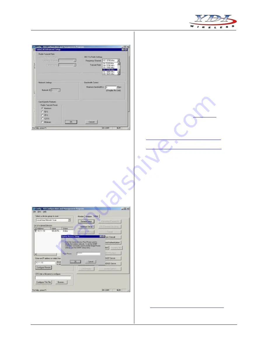
Figure 16 – 802.11 Advanced Setup Screen
10. The Marquee Bridge is optimized for a transmit rate
of 36 Mbps and the transmit power is preset from
factory with the proper value.
NOTE:
Make sure the output power is set to 50%
when using a sector antenna (see Table 1).
11. Click
OK
. Click
OK
again.
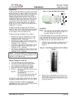
12. Click the
System Access
button. The corresponding
screen appears (see Figure 17). Enter a Pass
Phrase to identify the wireless network. All units
must be configured with the sam e value. Click
OK
.
Figure 17 – System Access Setup Screen
13. Go to
File
and click
Save Config
: this will save the
new settings.
14. After the Marquee Bridge is finished saving its
configuration, exit the YDI AP Manager program.
The Marquee Bridge is ready to use. Refer to the
online help for complete instructions on setting up
other features in the unit.
Technical Support
Your primary source of assistance is the dealer from
which you purchased this product. The YDI support staff
should only be contacted directly if you purchased this
product directly from YDI.
NOTE:
Before you contact Technical Support, please
make sure that you have read and thoroughly
understood all instructions outlined on this
manual.
YDI Wireless
Tel.:
703-205-0600
8000 Lee Highway
Fax:
703-205-0610
Falls Church, VA 22042
E-mail: [email protected]
USA
www.ydi.com
The latest software and User’s Manuals can also be
found at:
http://www.ydi.com/support/downloads.php
http://www.ydi.com/support/documents.php
FCC NOTICE
This equipment complies with FCC radiation exposure
limits set forth for an uncontrolled environment when
installed as directed. The equipment is intended for
professional installation only on fixed outdoor structures,
for p-p and p -mp operation in the ISM band. This
equipment should be installed and operated such that
there is a minimum of 2 meters of separation distance
between the equipment and all persons during normal
operation. If you are using a 4 ft dish antenna, the
minimum separation distance must be 2.56 meters.
The installer must avoid the main beam of the antenna
and point it to locations not occupied by persons during
the installation.
This device complies with part 15 of the FCC rules.
Operation is subject to the following two conditions:
(1) This device may not cause harmful interference, and
(2) This device must accept any interference received,
including interference that may cause undesired
operation.
NOTE:
The manufacturer is not responsible for any
radio or TV interference caused by
unauthorized modifications to this equipment.
Such modifications could void the user's
authority to operate the equipment.
To see all our FCC certified systems, please visit:
http://www.ydi.com/deployinfo/fcc-info.php
Table 1 lists the recommended YDI antennas that can
be used with the Marquee Bridge-EXT.


