10
SHUTDOWN
The fluids within the chiller-heater itself
need no preparation for freezing conditions.
Only the fluids in the chilled water and
cooling water circuits need to be addressed
during potentially freezing conditions.
When the equipment is located outdoors
in climates subject to freezing, cooling water
should be drained from the chiller-heater,
fluid circuit piping, and cooling tower at the
end of the cooling season. Use glycol of
adequate concentration in the chilled water
and heat medium circuits to prevent freeze
damage. The glycol will reduce the cooling
and heating capacity but this may be offset
somewhat by increasing the circuit fluid flow
rate. If in doubt about potential freeze
damage in your area, discuss it with your
ASP. Damage to the unit due to freezing is
not covered by the product warranty.
If a unit is to be shut down for the winter,
but no fluid circuits are to be drained, then
simply Disable the chiller-heater and allow
the unit to complete its Post Dilution Cycle.
Once completed, it is safe to leave the unit
as it sits for the off-season. Take
appropriate measures to ensure the fluids in
all fluid circuits are protected from freezing
(glycol, heat tape, etc.)
.
If a chiller-heater is to be shut down long-
term, then fluid circuits should be drained.
Disable the chiller-heater and allow the unit
to complete its Post Dilution Cycle. Once
completed, turn off the breaker on the unit
control panel. Then drain each fluid circuit.
Once drained, make sure to blow in both
directions
through
each
circuit
with
compressed air
(or similar)
to make sure no
significant amount of liquid remains inside
them. Close all isolation valves so as to
isolate the unit from the rest of the respective
fluid circuit. Pressurize each fluid circuit in
the chiller-heater with dry nitrogen to a
pressure of 1-2 PSI (7-14 kPa) to help inhibit
corrosion in the circuit during storage. It may
be desirable to break the vacuum in the
chiller-heater itself as well. If doing so,
pressurize the unit to the same pressure as
the circuits using nitrogen. See the Service
Manual for further details.
TROUBLESHOOTING
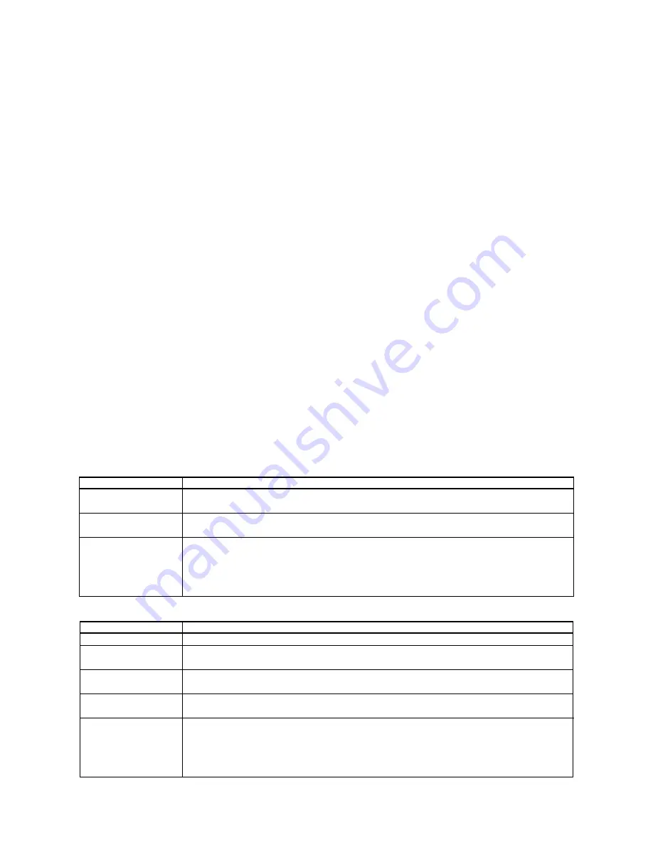
SYMPTOM: Chiller-heater does not operate.
Possible Cause
REMEDY
No High Voltage
Check the LED for the Power indication on the Control Panel. If it is not illuminated, check the
main power disconnect, fuses, and breakers.
Solution Pump Not
Running
Check the THRP overload switch. Check the GP temperature. Until the GP temperature rises
above 190°F
(88°C)
, the solution pump may remain off until the GP temperature warms up.
Chiller-heater is not
running but WTO
temperature is above
set point.
Nothing may be wrong. If the system chilled water loop has satisfied by reaching the desired set
point, the unit will shut down until the WTO sensor reads a temperature 3.6°F
(2°C)
above the set
point temperature, no matter how long that may take. To force operation, turn off power to the
chiller-heater, leave power off for 10 seconds, and then restore power. The chiller-heater should
start up if the WTO sensor reading is above the set point.
SYMPTOM: Poor cooling capacity.
Possible Cause
REMEDY
Poor Vacuum
Evacuate the machine per normal maintenance procedure. A leak check may also be necessary.
High Inlet Cooling
Water Temperature
Check the cooling tower fan. Check the cooling tower fluid level.
Low Cooling Water
Flow Rate
Check the cooling tower sump and cooling water circuit strainers.
Condenser/Absorber
Fouling, Scale Buildup
Check the cooling water circuit strainers. A chemical de-scaling procedure will be necessary.
Everything appears
normal but the leaving
chilled water
temperature is too
high.
Nothing may be wrong. If the load of the chilled water circuit exceeds the capacity of the chiller-
heater, the system will find equilibrium at a higher leaving chilled water temperature. If the
temperature drop through the chilled water loop is approximately 8-12°F
(4-6°C)
, then the unit
may actually be giving its full capacity and its capacity simply may not be enough. Check for
reasons that the load may have artificially increased
(open doors, new equipment, leaking valves, etc.)
Summary of Contents for CH-K100
Page 15: ......


