background image

11

O P E R A T I N G   M A N U A L

GB

MEASUREMENTS 

Depending on the actual position of the range switch in the display three significant digits and the unit of the measured quantity will be 

displayed. If it is necessary to replace the battery the multimeter indicates this displaying the battery symbol. If before the measured 

value the “-” symbol is displayed, then the measured value has an opposite polarization in relation to the connection of the meter. If 

the symbol „O.L” is displayed, the measurement range has been exceeded, and it is necessary to increase the measurement range. In 

case of measurements of quantities of unknown values the meter should be switched to „AUTO”, where it will automatically determine 

the adequate measurement range.

ATTENTION! The measurement range of the meter must not be lower than the measured value. It might damage the meter 

and cause an electric shock.

The correct connection of the leads: 

The red lead must be connected to the socket marked as „INPUT” or „10A”

The black lead must be connected to the socket marked as „COM”

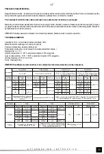
In order to ensure the highest possible precision of the measurements the optimum measurement conditions must be observed: 

ambient temperature between 18°C and 28°C and relative humidity <75 %

Determination of precision

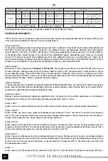
Precision: ± % of the indi weight of the least significant digit 

Measurement of the direct voltage: 1,396 V

Precision: ± (0,8% + 5)

Calculation of the error: 1,396 x 0,8% + 5 x 0,001 = 0, 0,005 = 0,016168 

Result of the measurement: 1,396 V ± 0,016 V

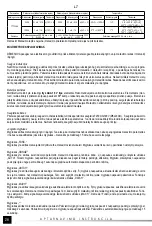
Measurements of the voltage

Connect the measurement cables to the sockets marked as „INPUT” and „COM”. Switch the range selector to the position of the 

measurement of the direct voltage or alternating voltage. Connect the measurement cables in parallel to the electric circuit and read 

the result of the Measurements of the voltage. Do not ever measure a voltage exceeding 300 V. It might damage the meter and cause 

an electric shock.

Measurement intensity of the current

Depending on the expected value of the measured intensity of the current connect the measurement cables to the socket marked as 

„INPUT” and „COM” or to the socket marked as „10A” and „COM”. Use the knob to select the correct measurement range, and the 

button „FUNC.” To select the kind of the measured current. The maximum intensity of the current measured through the „mA” socket 

may amount to 200 mA. In case of measurements of the current exceeding 200 mA, connect the lead to the socket marked as „10A”. 

The maximum intensity of the current measured through the socket marked as „10A” may amount to 10 A and it is not protected with 

a fuse. Therefore the duration of the measurements of currents exceeding 2 A must not exceed 15 seconds, and then it is required 

to wait at least 15 minutes before the next measurement. The maximum power-carrying capacity of the „mA” socket amounts to 200 

mA. 

The maximum current and voltage values of the sockets must not be exceeded.

 Connect the measurement cables in series 

to the tested electric circuit, select the range and kind of the current and read the result of the measurement. The first stage of the 

measurements is to select the maximum measurement range. In order to ensure more precise results of the measurement you may 

change the measurement range. 

Measurements of resistance


Connect the measurement cables to the sockets marked as „INPUT” and „COM” and switch the range selector to the measurements of 

resistance. Place the measurements leads at the terminals of the measured element and read the result of the measurement. In order 

to ensure more precise results of the measurements, the measurement range may be changed if required. 

It is strictly prohibited to 

measure the resistance of live elements. 

In case of measurements of values exceeding 1M

Ω

 the measurement may take a couple 

of seconds before the result is stable, which is a normal reaction during measurements of high resistances.

Before the measurement leads are placed at the measured element the symbol „O.L” is displayed.

Measurement of capacity

Connect the measurement cables to the sockets marked as „INPUT” and „COM”; switch the range selector to the measurement 

of capacity. Make sure the capacitor was discharged before the measurement. 

Do not ever measure the capacity of a charged 

capacitor, since it might damage the meter and cause an electric shock. 

In case of measurements of high-capacity condensers 

the measurement may last approximately 30 seconds before the result is stable.

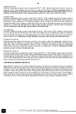
Diode test 

Connect the measurement cables to the sockets marked as „INPUT” and „COM” and switch the selector to the diode symbol. Use 

the „FUNC.” Button to select diode test, after which the diode symbol will be displayed. Place the measurement leads at the diode 

terminals in the conduction direction and the reverse direction. If the diode is functioning correctly, then at the diode connected in the 

Summary of Contents for YT-73084

Page 1: ...CYFROWY DIGITAL MULTIMETER DIGITALES MULTIMETER SKAITMENINIS MULTIMETRAS CIPARU MULTI M R T JS DIGIT LN MULTIMETR DIGIT LNY MULTIMETER DIGIT LIS MULTIM TER APART DIGITAL DE MASURAT MULTIMETRO DIGITAL...

Page 2: ...d ky m c ho p stroje 6 m c vodi e 1 merac pr stroj 2 displej 3 prep na 4 ovl dacie tla idl 5 zdierky meracieho pr stroja 6 meracie vodi e 1 m r m szer 2 kijelz 3 v laszt kapcsol 4 vez rl gombok 5 a m...

Page 3: ...e na nutnos separovan ho zberu opotrebovan ch elektrick ch a elektronick ch zariaden Opotrebovan elektrick zariadenia s zdrojom druhotn ch surov n je zak zan vyhadzova ich do kontejnerov na komun lny...

Page 4: ...Rezistence Odpor Odpor Ellen ll s Rezisten omic Resistencia Pojemno Capacity Kapazit t Talpa Tilpums Kapacita Kapacita Kapacit s Capacitatea Capacidad U D C 0 300V I D C 0 10A U A C 0 300V I A C 0 10...

Page 5: ...Dok adno YT 73084 200 mV 0 1 mV 0 8 5 2 V 1 mV 1 0 5 200 A 0 1 A 1 2 5 200 A 0 1 A 1 5 5 2 V 1 mV 20 V 10 mV 2 mA 1 A 2 mA 1 A 20 V 10 mV 200 V 0 1 V 20 mA 10 A 20 mA 10 A 200 V 0 1 V 300 V 1 0 V 1 2...

Page 6: ...nik na nowy Przycisk w cznika Przycisk s u y do w czania i wy czania miernika W przypadku gdy nie b dzie wykonywany pomiar przestawiany wybierak ani naciskany aden inny przycisk miernik wy czy si samo...

Page 7: ...ne nat enie mierzonego pr du w gnie dzie mA mo e wynosi 200 mA w przypadku pomiaru pr du wy szego ni 200 mA nale y pod czy przew d do gniazda 10A Maksymalne nat enie mierzonego pr du w gnie dzie 10A m...

Page 8: ...go pod czenia odczytujemy wynik pomiaru wsp czynnika wzmocnienia pokazany na wy wietlaczu Jest ab solutnie zabronione testowanie tranzystor w przez kt re przep ywa pr d elektryczny Pomiar temperatury...

Page 9: ...ision Range Resolution Precision YT 73084 200 mV 0 1 mV 0 8 5 2 V 1 mV 1 0 5 200 A 0 1 A 1 2 5 200 A 0 1 A 1 5 5 2 V 1 mV 20 V 10 mV 2 mA 1 A 2 mA 1 A 20 V 10 mV 200 V 0 1 V 20 mA 10 A 20 mA 10 A 200...

Page 10: ...ff If no measurement is realised the selector remains in the same position and no other button is pushed the meter will turn out automatically after approximately 15 minutes Button FUNC The purpose of...

Page 11: ...hrough the mA socket may amount to 200 mA In case of measurements of the current exceeding 200 mA connect the lead to the socket marked as 10A The maximum intensity of the current measured through the...

Page 12: ...ection is correct read the displayed result of the measurement of the gain coefficient It is strictly prohibited to test live transistors Measurement of temperature Connect the thermoelement leads to...

Page 13: ...Messger tes berschreiten ist ver boten Parameter Gleichspannung Wechselspannung Gleichstrom Wechselstrom RIN 10 M RIN 10 M fIN 40 400 Hz UAB 20 mV f r die Bereiche 200 A 20 mA 2 A UAB 200 mV f r die...

Page 14: ...essger tes ffnen und zwar durch Verdrehen des in der ffnung der Grundplatte auf der Unterseite des Messger tes sich befindenden Stellrades um 90 Die Batterie wird entsprechend der Kennzeichnung der Kl...

Page 15: ...n Die rote Leitung in die mit INPUT oder 10A gekennzeichnete Buchse die schwarze Leitung in die Buchse COM Um die gr te Messgenauigkeit zu erreichen muss man auch optimale Messbedingungen gew hrleiste...

Page 16: ...messung genutzt dann gibt der eingebaute Summer jedes Mal wenn der gemessene Widerstand unter 30 f llt einen Signalton ab Im Messbereich von 30 bis 100 kann auch ein Summton zu h ren sein Das Testen d...

Page 17: ...A 1 5 5 2 1 20 10 2 A 1 A 2 A 1 A 20 10 200 0 1 20 A 10 A 20 A 10 A 200 0 1 300 1 0 1 2 5 200 A 0 1 A 200 A 0 1 A 300 1 1 0 5 2A 1 A 2 0 10 2A 1 A 3 0 10 10 A 10 A 10 A 10 A 200 300 rms 300 d c 300 a...

Page 18: ...O C 1 3 400 O C 1000 O C 2 3 1000 A 1 1 A 1 2 5 1000 A 1 1 A 1 5 5 0 O F 1800 O F 1 O F 0 O F 50 O F 5 4 50 O F 750 O F 1 3 750 O F 1800 O F 2 3 300 d c a c rms UINma x 200 fIN 40 400 Hz 300 d c a c r...

Page 19: ...UT COM INPUT COM O L AUTO INPUT 10A COM 18 C 28 C 75 1 396 0 8 5 1 396 x 0 8 5 x 0 001 0 011168 0 005 0 016168 1 396 0 016 INPUT COM 300 INPUT COM 10A COM FUNC mA 200 A 200 A 10A 10A 10 A 2 A 15 15 A...

Page 20: ...20 RUS 1M O L INPUT COM 30 INPUT COM FUNC O L INPUT COM FUNC 30 30 100 hFE PNP NPN E B C INPUT COM Temp FUNC O F O C 250 O C K...

Page 21: ...A 1 5 5 2 1 20 10 2 A 1 A 2 A 1 A 20 10 200 0 1 20 A 10 A 20 A 10 A 200 0 1 300 1 0 1 2 5 200 A 0 1 A 200 A 0 1 A 300 1 1 0 5 2A 1 A 2 0 10 2A 1 A 3 0 10 10 A 10 A 10 A 10 A 200 300 rms 300 d c 300 a...

Page 22: ...O C 1 3 400 O C 1000 O C 2 3 1000 A 1 1 A 1 2 5 1000 A 1 1 A 1 5 5 0 O F 1800 O F 1 O F 0 O F 50 O F 5 4 50 O F 750 O F 1 3 750 O F 1800 O F 2 3 300 d c a c rms UINma x 200 fIN 40 400 Hz 300 d c a c r...

Page 23: ...OM INPUT COM O L AUTO INPUT 10A COM 18 C 28 C 75 1 396 0 8 5 1 396 x 0 8 5 x 0 001 0 011168 0 005 0 016168 1 396 0 016 INPUT COM 300 INPUT COM 10A COM FUNC mA 200 A 200 A 10A 10A 10 A 2 A 15 15 A 200...

Page 24: ...24 UA INPUT COM 30 V COM FUNC O L V COM FUNC 30 30 100 hFE PNP NPN E B C INPUT COM Temp FUNC O F O C 250 O C K...

Page 25: ...ov Kintamoji srov RIN 10 M RIN 10 M fIN 40 400 Hz UAB 20 mV diapazonams 200 A 20 mA 2 A UAB 200 mV diapazonams 2 mA 200 mA 10 A UAB 20 mV diapazonams 200 A 20 mA 2 A UAB 200 mV diapazonams 2 mA 200 mA...

Page 26: ...lis tai rei kia kad elementai yra i eikvoti ir reikia juos pakeisti naujais Matavim netikslumams i vengti baterijos simboliui i si vietus rekomenduojama kaip galint grei iau elementus pakeisti naujais...

Page 27: ...mosios tampos matavimo pozicij Matavimo laidus prijungti lygiagre iai elektros grandin s at vilgiu ir perskaityti tampos matavimo rezultat Niekada nematuoti tampos vir ijan ios 300 V To pasekm je matu...

Page 28: ...zistoriaus tipo jungiame j prie pastovo lizdo pa enklinto sumboliu PNP arba NPN i rint kad tranzistoriaus kojel s atsirast tinkamose vietose pa enklintose raid mis E emiteris B baz C kolektorius Tvark...

Page 29: ...A 2 A UAB 200 mV diapazoniem 2 mA 200 mA 10 A UAB 20 mV diapazoniem 200 A 20 mA 2 A UAB 200 mV diapazoniem 2 mA 200 mA 10 A fIN 40 400 Hz Kataloga Nr Diapazons Iz ir ana Precizit te Diapazons Iz ir an...

Page 30: ...i P c tam kad nor d s baterijas simbols ir nepiecie ami main t bateriju uz jaunu Lai saglab t m r juma precizit ti rekomend jam main t baterijas vis tr k p c baterijas simbola par d anas Dro in t ja...

Page 31: ...bas dei un p rbaud t sprieguma m r juma rezult tu Nedr kst m r t spriegumu augst ku par 300 V Tas var ierosin t m r t ja boj anu un elektrisku triecienu Str vas stipruma m r ana Atkar gi no str vas st...

Page 32: ...gt pie ligzdas apz m tas ar PNP vai NPN kontrol jot lai tranzistora kontakti b tu novietoti viet s apz m tas ar burtiem E emiters B b ze C kolektors Darbder ga tranzistora un pareizas piesl g anas ga...

Page 33: ...400 Hz UAB 20 mV pro rozsahy 200 A 20 mA 2 A UAB 200 mV pro rozsahy 2 mA 200 mA 10 A UAB 20 mV pro rozsahy 200 A 20 mA 2 A UAB 200 mV pro rozsahy 2 mA 200 mA 10 A fIN 40 400 Hz Katalogov Rozsah Rozli...

Page 34: ...a zajist te Kdy se na displeji zobraz symbol baterie znamen to e je t eba baterie vym nit za nov K zaji t n p esnosti m en se doporu uje baterie vym nit co nejd ve po zobrazen symbolu baterie V m na p...

Page 35: ...paraleln k elektrick mu obvodu a ode t te v sledek m en nap t Nikdy nem te nap t vy ne 300 V Mohlo by doj t ke zni en m c ho p stroje a razu elekt inou M en proudu V z vislosti na p edpokl dan velikos...

Page 36: ...eny ke kontakt m ozna en m p smeny E emitor B b ze C kolektor V p pad e je tranzistor bezchybn a spr vn p ipojen ode teme v sledek m en zesilovac ho initele kter se zobraz na displeji Je absolutn zak...

Page 37: ...n pr d Striedav pr d RIN 10 M RIN 10 M fIN 40 400 Hz UAB 20 mV pre rozsahy 200 A 20 mA 2 A UAB 200 mV pre rozsahy 2 mA 200 mA 10 A UAB 20 mV pre rozsahy 200 A 20 mA 2 A UAB 200 mV pre rozsahy 2 mA 200...

Page 38: ...na spodnej strane pr stroja v otvore podstavca o 90 Bat rie pripojte ku kontaktom pod a ich ozna enia skrinku zatvorte a zaistite oto en m kolieska Ak sa na displeji zobraz symbol bat rie znamen to e...

Page 39: ...jednosmern ho nap tia 1 396 V Presnos 0 8 5 V po et chyby 1 396 x 0 8 5 x 0 001 0 011168 0 005 0 016168 V sledok merania 1 396 V 0 016 V Meranie nap tia Meracie vodi e pripojte do zdierok ozna en ch I...

Page 40: ...nia tranzistora V z vislosti od typu sk an ho tranzistora pripojte tranzistor do z suvky adapt ra ozna enej PNP alebo NPN Dbajte na to aby boli pr slu n v vody tranzistora pripojen v miestach ozna en...

Page 41: ...N 10 M RIN 10 M fIN 40 400 Hz UAB 20 mV 200 A 20 mA 2 A tartom nyokra UAB 200 mV 2 mA 200 mA 10 A tartom nyokra UAB 20 mV 200 A 20 mA 2 A tartom nyokra UAB 200 mV 2 mA 200 mA 10 A tartom nyokra fIN 40...

Page 42: ...rgat gomb 90O kell t rt n elford t s val Helyezze be az elemet a p lusok jel l s nek megfelel en z rja be a burkolatot s forgassa el a forgat gombot Ha megjelenik az elem jele az azt jelenti hogy ki k...

Page 43: ...68 M r si eredm ny 1 396 V 0 016 V Fesz lts gm r s Csatlakoztassa a m r vezet keket az INPUT s a COM jel dugaszol aljzatokba A m r si m d kapcsol t a m rend egyen vagy v ltakoz fesz lts gnek megfelel...

Page 44: ...E el jelzett ll sba a tranzisztor er s t si t nyez j nek m r se A rendelkez sre ll tranzisztor t pus t l f gg en a dugaszol aljzathoz csatlakoztatjuk a PNP vagy NPN jel aljzatot gyelve arra hogy a tra...

Page 45: ...at Parametru Voltaj curent continuu Voltaj curent alternativ Curent continuu Curent alternativ RIN 10 M RIN 10 M fIN 40 400 Hz UAB 20 mV pentru intervale 200 A 20 mA 2 A UAB 200 mV pentru intervale 2...

Page 46: ...0O comutatorul de reglare situat n orificiul suportului situate pe partea dorsal a aparatului de m surat Cupla i bateria conform conform marcajului clemelor nchide i carcasa i roti i comutatorul de re...

Page 47: ...ctitate 0 8 5 Evaluare eroare 1 396 x 0 8 5 x 0 001 0 011168 0 005 0 016168 Rezultat m sur toare 1 396 V 0 016 V M surare tensiune Cupla i conductorii de m surare la soclurile marcate cu INPUT i COM S...

Page 48: ...ric Test tranzistori Comutatorul pentru intervale de m surare trebuie setat n pozi ia marcat cu simbolul hFE m surare coeficient de amplificare tran zistor n func ie de tipul de tranzistor posedat cup...

Page 49: ...nua Tensi n alterna Corriente continua Corriente alterna RIN 10 M RIN 10 M fIN 40 400 Hz UAB 20 mV para los rangos 200 A 20 mA 2 A UAB 200 mV para los rangos 2 mA 200 mA 10 A UAB 20 mV para los rangos...

Page 50: ...ferior del medidor Conecte las bater as de acuerdo con las indicaciones de los bornes cierre la caja y gire la perilla Si en la pantalla aparece el s mbolo de bater a es menester reemplazarla Para gar...

Page 51: ...5 C lculo del error 1 396 x 0 8 5 x 0 001 0 011168 0 005 0 016168 Resultado de la medici n 1 396 V 0 016 V Medici n de la tensi n Conecte los cables de medici n a las entradas indicadas con los s mbo...

Page 52: ...e proh be terminantemente realizar pruebas de de la conducci n en circuitos bajo tensi n Prueba de transistores Ponga el selector de los rangos de medici n en la posici n indicada con el s mbolo hFE m...

Reviews: