


4.4 Powering Up the Drive
u
Powering Up the Drive and Operation Status Display
n
Powering Up the Drive
Review the following checklist before turning the power on.
Item to Check
Description
Power supply voltage
208 Vac: Three-phase 200 to 240 Vac 50/60 Hz
480 Vac: Three-phase 380 to 480 Vac 50/60 Hz
Properly wire the power supply input terminals (L1, L2, L3).
Check for proper grounding of drive and motor.
Drive output terminals and
motor terminals
Properly wire drive output terminals T1, T2, and T3 with motor terminals U, V, and W.
Control circuit terminals
Check control circuit terminal connections.
Drive control terminal status
Open all control circuit terminals (off).
Status of the load and connected
machinery
Decouple the motor from the load.
n
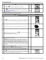
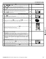
Status Display
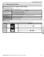
When the power supply to the drive is turned on, the HOA keypad lights will appear as follows:
Status
Name
Description
Normal
Operation
LO
RE
ESC
RUN
STOP
ENTER
RESET
DIGITAL OPERATOR JVOP-183
ALM
DRV-OFF
U1-01= 00.00Hz
U1-02= 0.00Hz
U1-03= 0.00 A
Freq Ref (AUTO)
LSEQ
LREF
RLY
DRV/BYP
The data display area displays the frequency reference.
is lit.
Fault
LO
RE
ESC
RUN
STOP
ENTER
RESET
DIGITAL OPERATOR JVOP-180
ALM
DRV-FAULTED
FB01
Safety Open
RLY
DRV/BYP
External fault (example)
Data displayed varies by the type of fault.
Refer to Fault Displays, Causes, and Possible
and
are lit.
4.4 Powering Up the Drive
YASKAWA ELECTRIC SIEP YAIZ1B 01E YASKAWA AC Drive – Z1000 Bypass Technical Manual
103
4
Start-Up Programming & Operation


