YASKAWA SI-ES3 Installation Manual Download Page 43

10  Examples

YASKAWA ELECTRIC

 TOBP C730600 96C YASKAWA AC Drive Option SI-ES3 Installation Manual

 43

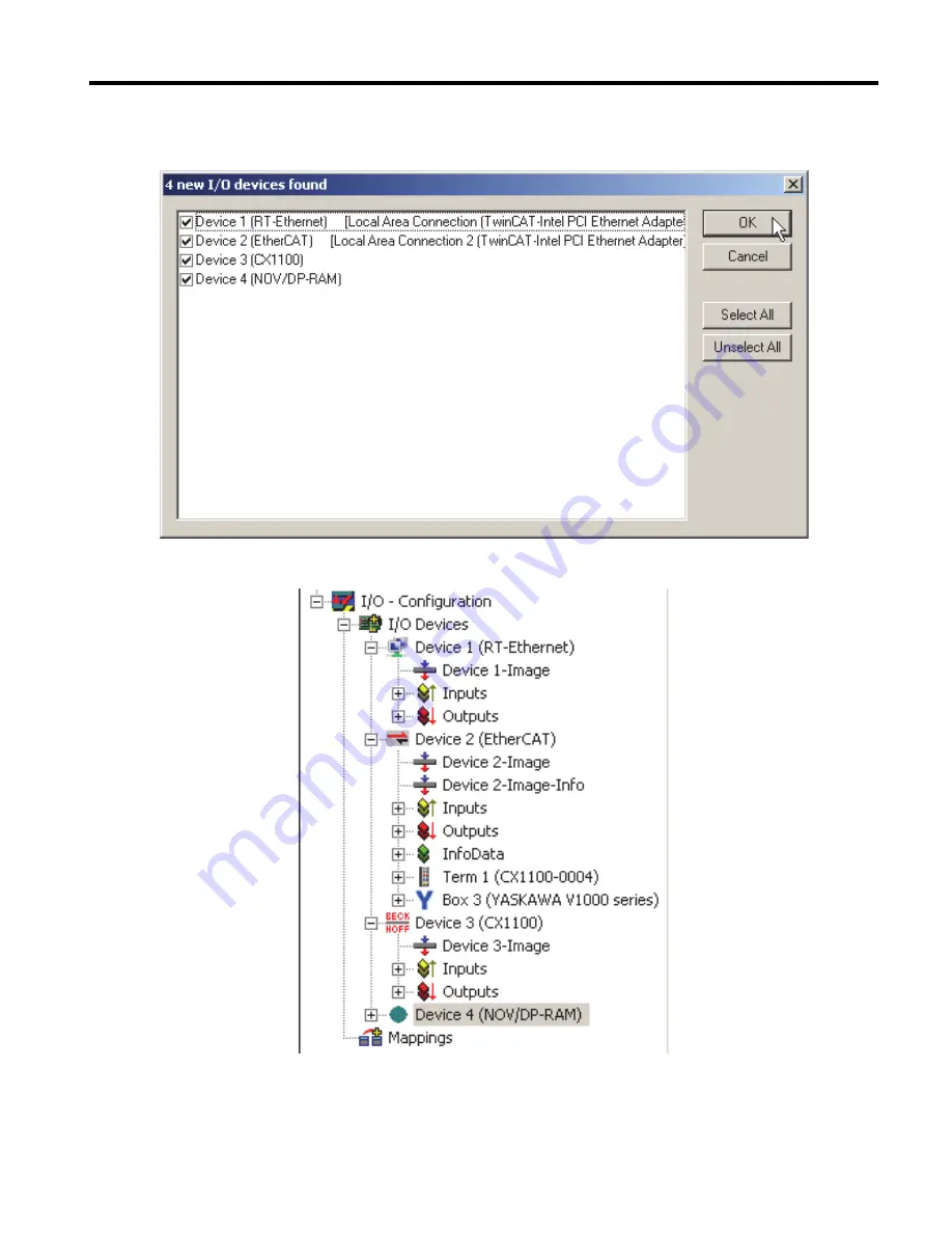
3. Make sure the EtherCAT device (line two in the graphic) is selected and confirm with 

OK

.

Figure 21  

4. TwinCAT System Manager will ask you to scan for boxes. Select Yes.

Figure 22  

GEM_EtherCAT_IM_E_conditional.book  43 ページ  2018年10月25日 木曜日 午後7時29分

Summary of Contents for SI-ES3

Page 1: ...l Type SI ES3 To properly use the product read this manual thoroughly and retain for easy reference inspection and maintenance Ensure the end user receives this manual 製品を安全にお使いいただくために 本書を必ずお読みください また 本書をお手元に保管していただくとともに 最終的に本製品をご使用になる ユーザー様のお手元に確実に届けられるよう お取り計らい願います MANUAL NO TOBP C730600 96C ...

Page 2: ...t the prior written permission of Yaskawa No patent liability is assumed with respect to the use of the information contained herein Moreover because Yaskawa is constantly striving to improve its high quality products the information contained in this manual is subject to change without notice Every precaution has been taken in the preparation of this manual Yaskawa assumes no responsibility for e...

Page 3: ...PRECAUTIONS 4 2 OVERVIEW 8 3 RECEIVING 9 4 ETHERCAT OPTION COMPONENTS 10 5 MECHANICAL ELECTRICAL INSTALLATION 15 6 ETHERCAT OPTION RELATED DRIVE PARAMETERS 30 7 SUPPORTED MODES OF OPERATION 32 8 OBJECT DICTIONARY 33 9 PROCESS DATA OBJECTS PDO 36 10 EXAMPLES 39 11 TROUBLESHOOTING 45 12 EUROPEAN STANDARDS 51 13 SPECIFICATIONS 54 ...

Page 4: ...ons before using the product n About Terms and Abbreviations in This Document Representations Used in This Manual Description Option YASKAWA AC Drive Option EtherCAT Drive YASKAWA AC Drive 1000 Series A1000 YASKAWA AC Drive GA700 YASKAWA AC Drive GA800 Keypad LCD Operator for YASKAWA AC Drive 1000 Series LED Operator for YASKAWA AC Drive 1000 Series LCD Keypad for YASKAWA AC Drive GA700 and GA800 ...

Page 5: ...rvicing this option The option must be installed according to this manual and local codes The following conventions are used to indicate safety messages in this manual Failure to heed these messages could result in serious or possibly even fatal injury or damage to the products or to related equipment and systems DANGER Indicates a hazardous situation which if not avoided will cause death or serio...

Page 6: ... the content and presentation of the manual may be changed without notice to improve the product and or the manual Contact Yaskawa or a Yaskawa representative and provide the manual number shown on the front cover to order new copies of the manual DANGER Heed the safety messages in this manual Failure to comply will cause death or serious injury The operating company is responsible for any injurie...

Page 7: ...amage to the drive or option and will void warranty Yaskawa is not responsible for any modification of the product made by the user Do not expose the drive or the option to halogen group disinfectants Do not pack the drive or the option in fumigated or sterilized wooden materials Do not sterilize the entire package after packing the product Failure to comply could damage electrical components in t...

Page 8: ...ion The EtherCAT Option supports the following communication profiles DS 301 Ver 4 02 DSP 402 Ver 3 0 Velocity Mode Figure 1 Figure 1 EtherCAT Conformance tested u Compatible Products The option can be used with the products in Table 1 Table 1 Compatible Products Note Refer to the option package labeling in the field designated PRG four digit number or the option nameplate designated V option soft...

Page 9: ...ely Verify receipt of the correct model by checking the information Find the model number on the nameplate on the PCB If you have received the wrong option card model or the Communication Option card does not function properly contact Yaskawa or a Yaskawa representative u Content and Packaging Table 2 Option Package Contents for Inverter Drives u Tools Required A Phillips screwdriver PH1 1 or PH2 ...

Page 10: ...EDs on page 11 for details on the LEDs 2 Connect the provided ground wire during installation Installation on GA700 and GA800 drives does not require the ground wire G Model number B Installation hole H Ground terminal installation hole 2 C LED RUN 1 D LED ERR I Communication cable connector OUT JP3 E LED L A OUT 1 F LED L A IN 1 J Communication cable connector IN JP2 Underside A Looking from the ...

Page 11: ...rnet Link Activity 1 and 2 The Link Activity indicators show the status of the physical link and show activity on the link period LED Color Display Meaning L A OUT L A IN Off No link The communication cable is not physically connected The communication controller is not started up Green On The module is connected to Ethernet A communication cable is physically connected but no data is being exchan...

Page 12: ...g for commands from the drive 6 Hz Firmware loader protocol is processing commands LED Color Display Meaning ERR Off No link The communication option card is in working condition Red Blinking General configuration error Single Flash The slave device application has changed the communication state autonomously The parameter Change in the AL status register is set to 01 Hex change error Double Flash...

Page 13: ...re 4 Meaning of LED Flash Rates Flickering on 50 ms 200 ms 200 ms 200 ms 200 ms 200 ms 200 ms 200 ms 200 ms 200 ms 200 ms 200 ms 200 ms 200 ms 200 ms 200 ms 200 ms 200 ms 1 2 n 200 ms 1000 ms 1000 ms 1000 ms 1000 ms 1000 ms 200 ms off on off on off on off on off on off on off Blinking Single Flash Double Flash Triple Flash n Flashes Inverted Double Flash ...

Page 14: ...t5e or better communication cables n Network Termination If the drive is the last node in the network network termination is automatically realized by the ASIC of the Communication Option card EtherCAT Connector Pin Signal Description Figure 5 1 TD Send data 2 TD Send data 3 RD Receive data 4 N C Pins denoted as N C do not connect to any signal 5 N C Pins denoted as N C do not connect to any signa...

Page 15: ...indicators are OFF measure for unsafe voltages to confirm the drive is safe WARNING Electrical Shock Hazard Do not operate equipment with covers removed Failure to comply could cause death or serious injury The diagrams in this section may include options and drives without covers or safety shields to illustrate details Reinstall covers and shields before operating the drive and run the drive acco...

Page 16: ...ly could cause ESD damage to circuitry Never connect or disconnect the motor from the drive while the drive is outputting voltage Improper equipment sequencing could damage the drive Do not connect or operate any equipment with visible damage or missing parts Failure to comply could further damage the equipment Do not use unshielded wire for control wiring Failure to comply may cause electrical in...

Page 17: ...a Drive Procedures for installing and wiring options differ depending on the drive model Refer to Table 4 to check the procedures for installing and wiring options on a drive Table 4 Procedures for Installing and Wiring Options on a Drive Product Series Procedures for Installing and Wiring Options on a Drive Page A1000 Procedure A 18 GA700 Procedure B 24 GA800 Procedure B 24 ...

Page 18: ...f the drive with the option and related components for reference in the installation procedure Figure 6 Figure 5 Drive Components with Option A Insertion point for CN5 connector K Option modular connector IN B SI ET3 option L Drive grounding terminal FE C Drive front cover M Connector CN5 A D Keypad N Connector CN5 B Not available for communication option installation E LED label F Drive terminal ...

Page 19: ...nnect all power to the equipment and wait for at least the time specified on the warning label The internal capacitor remains charged even after the drive is de energized The charge indicator LED will extinguish when the DC bus voltage is below 50 Vdc When all indicators are OFF measure for unsafe voltages to confirm the drive is safe 1 Shut off power to the drive wait the appropriate amount of ti...

Page 20: ...he appropriate position on the drive front cover C Figure 8 Figure 7 Affix the LED Label 3 Insert the option card B into the CN5 A M connector on the drive and fasten it into place using one of the included screws H Tighten the screw to 0 5 to 0 6 N m 4 4 to 5 3 in lb Figure 9 Figure 8 Insert the Option L A IN RUN L A OUT ERR C E A1000 NS MS M H B A1000 ...

Page 21: ... screws H Connect the other end of the ground wire I to the remaining ground terminal and installation hole on the option B using the last remaining provided screw H Tighten both screws to 0 5 to 0 6 N m 4 4 to 5 3 in lb Figure 10 Figure 9 Connect the Ground Wire Note The drive has only two ground terminal screw holes I Two ground wires should share the same ground terminal when connecting three o...

Page 22: ...the left side of the front cover as shown in Figure 10 A to create the necessary openings on these models Refer to the Peripheral Devices Options section of the drive instruction manual for more information Note Separate communication cables from main circuit wiring and other electrical lines to avoid potential sources of electrical interference Figure 11 Figure 10 Wire Routing Examples A Route wi...

Page 23: ...nications cables apart from main circuit wiring and other electrical and power lines Ensure the cable end is firmly connected see Figure 18 7 Reattach the drive front covers C F and the keypad D NOTICE Do not pinch cables between the front covers and the drive Failure to comply could cause erroneous operation Figure 12 Figure 11 Replace the Front Covers and Keypad 8 Set drive parameters in Table 5...

Page 24: ...ed with the drive 2 Make sure that the drive functions correctly Refer to Figure 12 for an exploded view of the drive with the option and related components for reference in the installation procedure Figure 13 Figure 12 Drive Components with Option A Insertion point for CN5 connector I LED Status Ring board B SI ET3 option J Connector CN5 A C Included screws K Connector CN5 B Not available for co...

Page 25: ...l Shock Hazard Do not inspect connect or disconnect any wiring while the drive is energized Failure to comply will cause death or serious injury Before servicing disconnect all power to the equipment and wait for at least the time specified on the warning label The internal capacitor remains charged even after the drive is de energized The charge indicator LED will extinguish when the DC bus volta...

Page 26: ... removal NOTICE Damage to Equipment Observe proper electrostatic discharge ESD procedures when handling the option drive and circuit boards Failure to comply could cause ESD damage to circuitry Figure 15 Figure 14 Remove the Front Cover and Keypad Keypad connector Keypad connector tab Move the keypad connector to the holder on the drive after removing the keypad and before removing the front cover...

Page 27: ... to comply could cause erroneous operation and damage the drive Figure 16 Figure 15 Remove the LED Status Ring Board 4 Insert the option card B into the CN5 A connector J on the drive and fasten it into place using the included screws C Tighten both screws to 0 5 to 0 6 N m 4 4 to 5 3 in lb Note Installing the option card on GA700 and GA800 drives requires only two screws and does not require a gr...

Page 28: ...e 18 6 Reattach the LED Status Ring board I Use the open space provided inside the LED Status Ring board to route option wiring NOTICE Do not pinch cables between the front cover or the LED Status Ring board and the drive Failure to comply could cause erroneous operation 7 Reattach the drive front cover D and the keypad F Figure 18 Figure 17 Replace the Front Cover and Keypad 8 Set drive parameter...

Page 29: ... File For easy network implementation of drives equipped with a Communication Option card the ESI file can be obtained from these sources U S http www yaskawa com Europe http www yaskawa eu com Japan http www e mechatronics com Other areas Check the back cover of these manuals For questions contact Yaskawa or a Yaskawa representative 1 Connect the provided ground wire for installations on 1000 ser...

Page 30: ... Poles Set the number of motor poles described on the motor nameplate Relevant for DSP402 YASKAWA AC Drive 1000 Series 2 to 48 YASKAWA AC Drive GA700 GA800 2 to 120 4 F6 01 Operation Selection after Communications Error Determines drive response when a bUS error is detected during communications with the EtherCAT Option 0 Ramp to Stop 1 Coast to Stop 2 Fast Stop 3 Alarm Only 4 4 Alarm Run at d1 04...

Page 31: ... the drive software version For details refer to the technical manual for the drive 3 E2 04 is necessary to set up when the Drive Profile DSP402 objects are used Also refer to 9 4 If set to 3 or 4 then the drive will continue to operate when an EF0 fault is detected Take proper safety measures such as installing an emergency stop switch 5 Refer to the drive manual to know if settings 4 and 5 are a...

Page 32: ...cording the CANopen Device Profile and Motion Control DSP402 profile It also contains YASKAWA vendor specific CANopen objects based on the present CANopen option board specification The EtherCAT Option supports the following communication profiles DS 301 Ver 4 02 DSP 402 Ver 3 0 Velocity Mode To reset a mode a power cycle is necessary Note If an object of the range 6xxx is used the DSP402 mode is ...

Page 33: ...ror Register 1003 Pre defined Error Field 1008 Manufacturer Device Name 1009 Manufacturer Hardware Version 100A Manufacturer Software Version 1010 Store Parameters 1011 Restore Default Parameters 1018 Identity Object 1600 1628 Receive PDO Mapping 1A00 1A28 Transmit PDO Mapping 1C00 Sync Manager Communication Type 1C12 Sync Manager RxPDO assign 1C13 Sync Manager TxPDO assign Index Hex Name 2000 Ope...

Page 34: ...ble default none 3100 Selectable default none Index Hex Name 2100 Drive Status 2110 Output Frequency 2120 Output Current 2130 Output Torque Reference 2140 MEMOBUS Modbus Read Response 2150 MEMOBUS Modbus Write Response 2151 Advanced MEMOBUS Modbus Write Response 2155 PDO Parameter Write Response 2160 MEMOBUS Modbus Not Limited Enter Command Response 2180 Selectable default Input terminal status 21...

Page 35: ...Record 4001 Option Info Status Record 4010 Store Parameters 4011 Restore Default Parameters Index Hex Name 60FD Digital Inputs 60FE Digital Outputs 6502 Supported Drive Modes Index Hex Name 6040 Control Word 6041 Status Word 6060 Modes of Operation 6061 Modes of Operation Display Index Hex Name 6042 vl target velocity 6043 vl velocity demand 6044 vl control effort 6046 vl velocity min max amount 6...

Page 36: ... configuration PRE OPERATIONAL state TxPDOs are used to transfer data from the option card and RxPDOs are used to transfer data to the option card The Communication Option card supports at least 8 parameters mapped to RxPDO and 8 parameters mapped to TxPDO The drive supports 15 Receive and 16 Transmit PDOs The following tables show available PDOs their default settings and the objects required to ...

Page 37: ...vl Accel delta time 1A16 24 Sub index 1 6049 1 4 bytes vl Decel delta speed Sub index 2 6049 2 2 bytes vl Decel delta time 1A17 25 Sub index 1 604A 1 4 bytes vl quick stop delta speed Sub index 2 604A 2 2 bytes vl quick stop delta time 1A18 26 Sub index 1 604C 1 4 bytes vl Dimension factor Sub index 2 604C 2 4 bytes vl Dimension factor 1A19 36 Sub index 1 2100 1 2 bytes Drive status 1A23 37 Sub in...

Page 38: ...rd Sub index 2 60FE 1 4 bytes Physical digital outputs 1606 8 Sub index 1 6040 0 2 bytes DSP402 control word Sub index 2 6060 0 1 bytes DSP402 Modes of operation 1607 21 Sub index 1 6048 1 4 bytes Vl Accel delta speed Sub index 2 6048 2 2 bytes Vl Accel delta time 1614 22 Sub index 1 6049 1 4 bytes Vl Decel delta speed Sub index 2 6049 2 2 bytes Vl Decel delta time 1615 23 Sub index 1 604A 1 4 byt...

Page 39: ...ailable in a SPEED7 Studio project Note The graphics were created using SPEED7 Studio version 2016 clarify In other versions the software user interface may vary n Procedure 1 Click Extra Install device description file EtherCAT ESI to import the device description file for the communication option card 2 In the projecting view right click the EC Mastersystem 100 and select Add new device 3 In the...

Page 40: ...0 Examples 40 YASKAWA ELECTRIC TOBP C730600 96C YASKAWA AC Drive Option SI ES3 Installation Manual 4 Navigate to Vendor Yaskawa Electric Corporation Drives and select your inverter drive Confirm with OK ...

Page 41: ...10 Examples YASKAWA ELECTRIC TOBP C730600 96C YASKAWA AC Drive Option SI ES3 Installation Manual 41 n Result After following the procedure the YASKAWA inverter drive is ready for further use Figure 19 ...

Page 42: ...n option card available in a Beckhoff TwinCAT System Manager Note The graphics were created using TwinCAT System Manager version 2 11 In other versions the software user interface may vary n Procedure 1 Click Action Import XML Description to import the device description file for the communication option card 2 In the project tree right click I O Devices in the I O Configuration node and select Sc...

Page 43: ...30600 96C YASKAWA AC Drive Option SI ES3 Installation Manual 43 3 Make sure the EtherCAT device line two in the graphic is selected and confirm with OK Figure 21 4 TwinCAT System Manager will ask you to scan for boxes Select Yes Figure 22 ...

Page 44: ...10 Examples 44 YASKAWA ELECTRIC TOBP C730600 96C YASKAWA AC Drive Option SI ES3 Installation Manual n Result After following the procedure the YASKAWA inverter drive is ready for further use Figure 23 ...

Page 45: ... the noise source and use Surge Protective Device if necessary Use only recommended cables or other shielded line Ground the shield on the controller side or the drive input power side Separate all communication wiring from drive power lines and install a noise filter to the input side of the power supply for communication Minimize the effects of controller noise The option card is not properly co...

Page 46: ...nues replace the option card oFb00 Not supported An option card that is not compatible with the CN5 B connector was connected Connect the option card to the correct connector Note The option cards that can be connected to the CN5 B connector are the DO A3 AO A3 PG B3 and PG X3 Use the CN5 C connector when mounting only one PG option card oFb02 DuplicateOptions The same option card or the same type...

Page 47: ...erCAT WD time out If the EtherCAT watchdog time out is enabled Default in native XML description file and output data from PLC to the drive isn t updated in time an error will be triggered BUS Error is triggered in drive Error against drive will be cleared when the next lower to higher EtherCAT state transition is made Check network connection e g if cables plugged in at each node Check telegram t...

Page 48: ...erface protocol 2 Drive does not support this communication option card Drive fault OFx00 Option will log FATAL event record in NVS memory and set ERR LED solid RED Actions Check drive firmware version If drive firmware version is correct replace option card Replace the drive Option Error Description Error Indication Possible Solution I F proc time out Option card has not processed any drive syste...

Page 49: ...cations cable Repair disconnected cables and short circuits for proper wiring Replace a faulty communications cable with a normal one Programming error occurred on the controller side Check communications at start up and correct programming errors Communications circuitry is damaged Perform a self diagnostics check If the problem continues replace either the control board or the entire drive For i...

Page 50: ... start up and correct programming errors Communications circuitry is damaged Perform a self diagnostics check If the problem continues replace either the control board or the entire drive For instructions on replacing the control board contact Yaskawa or a Yaskawa representative Termination resistor setting for MEMOBUS Modbus communications is incorrect Enable the termination resistor in the last ...

Page 51: ...facturers the Low Voltage Directive for electronics manufacturers and the EMC guidelines for controlling noise This option displays the CE mark based on the EMC guidelines EMC Guidelines 2014 30 EU Drives used in combination with this option and devices used in combination with the drive must also be CE certified and display the CE mark When using drives displaying the CE mark in combination with ...

Page 52: ...nditions Verify the following installation conditions to ensure that other devices and machinery used in combination with this option and drives also comply with EMC guidelines 1 Use dedicated shield cable for the option and external device encoder I O device master or run the wiring through a metal conduit 2 Keep wiring as short as possible and ground the largest possible surface area of the shie...

Page 53: ...ce Models PG DI DO AI AO SI Figure 26 Figure 21 Option Installation for CE Compliance PG DI DO AI AO SI L1 L2 L3 L1 L2 L3 R CN5 B CN5 C CN5 A CN5 B CN5 C CN5 A S T PG Drive EMC filter PG option DI DO AI AO I O option SI Communication option Encoder I O device Master Cable clamp Enclosure panel Three phase power supply Cable clamp Cable clamp A1000 ...

Page 54: ...le DSP 301 Ver 4 02 DSP 402 Ver 1 1 Velocity Mode Connector RJ45 connector Communication Speed 10 100 Mbps Ambient Temperature 10 C to 50 C 14 F to 122 F Humidity up to 95 RH non condensing Storage Temperature 20 C to 60 C 4 F to 140 F allowed for short term transport of the product Area of Use Indoor free of corrosive gas airborne particles etc Altitude Up to 1000 m 3280 ft ...

Page 55: ...of Publication Revision Number Section Revised Content November 2018 2 All Addition Applicable product series Revision Reviewed and corrected entire documentation Back cover Revision Address June 2018 1 All Revision Reviewed and corrected entire documentation February 2018 First Edition MANUAL NO TOBP C730600 96B 1 Published in Japan June 2018 Date of publication Revision number A1000 ...

Page 56: ... 0099 Fax 66 2 017 0799 http www yaskawa co th YASKAWA ELECTRIC CHINA CO LTD 22F Link Square 1 No 222 Hubin Road Shanghai 200021 China Phone 86 21 5385 2200 Fax 86 21 5385 3299 http www yaskawa com cn YASKAWA ELECTRIC CHINA CO LTD BEIJING OFFICE Room 1011 Tower W3 Oriental Plaza No 1 East Chang An Ave Dong Cheng District Beijing 100738 China Phone 86 10 8518 4086 Fax 86 10 8518 4082 YASKAWA ELECTR...

Reviews: