background image

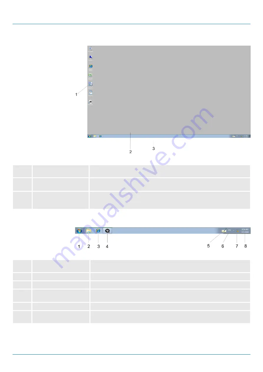
3.5.2  Structure

1

Icon

Via icons on the desktop you gain direct access to the application related to the

icon.

2

Desktop

The desktop is the screen that is shown after login at Windows

Ò

. It contains e.g.

links to the mostly used applications res. system components.

3

Task bar

The task bar is part of the desktop. When opening an application, a document or

a window, every running object is displayed as button on the task bar. Via this

buttons you may easily change between the open windows.

Basically the taskbar has the following structure:

1

Start button

This button offers you access to all components of your Panel PC such as appli-

cations, system settings, file browser etc.

2

Windows Explorer

The Windows Explorer is shown.

3

Internet Explorer

The Internet Explorer is shown.

4

Open applications

For every open application a button is to be found in the task bar. The switch

between the applications is performed via this buttons.

5

Software keyboard

This button displays a keyboard at the screen.

6

Keyboard layout

If you’ve connected a keyboard you may choose the requested language layout

via this button.

Task bar

HMI

Deployment Panel PC

Operating system Windows Embedded Standard 7 > Structure

HB160 | PPC | 67K-RSL0 | en | 22-20


32

Summary of Contents for PP010 ES

Page 1: ...PPC 67K RSL0 Manual HB160 PPC 67K RSL0 en 22 20 HMI Panel PC PPC010 ES...

Page 2: ...67K RSL0_000_PPC010ES 3 EN 2022 YASKAWA Europe GmbH Hauptstra e 185 65760 Eschborn Germany Tel 49 6196 569 300 Fax 49 6196 569 398 Email info yaskawa eu com Internet www yaskawa eu com...

Page 3: ...system 30 3 5 Operating system Windows Embedded Standard 7 31 3 5 1 General 31 3 5 2 Structure 32 4 BIOS setup 37 4 1 Overview 37 4 2 Main 38 4 3 Advanced 39 4 4 Chipset 49 4 5 Boot 54 4 6 Security 55...

Page 4: ...products mentioned are registered trademarks of Microsoft Inc USA All other trademarks logos and service or product marks specified herein are owned by their respective companies Every effort has bee...

Page 5: ...dge of automation technology n The manual consists of chapters Each chapter describes a completed topic n The following guides are available in the manual An overall table of contents at the beginning...

Page 6: ...ion department n commissioning n operation CAUTION The following conditions must be met before using or commis sioning the components described in this manual Hardware modifications to the process con...

Page 7: ...odules that have been damaged by electrostatic discharges can fail after a temperature change mechanical shock or changes in the electrical load Only the consequent implementation of protection device...

Page 8: ...itouch n Display resolution 1280 x 800 800 x 1280 n Processor Baytrail Intel Celeron J1900 Quad core 2GHz n Work memory 2x 204Pin DDR3 SO DIMM Socket 4GB DDR3 n User memory 16GB SSD SLC n CFast slot n...

Page 9: ...SB 3 0 7 2x USB A interface USB 2 0 8 RJ45 jack for Ethernet communication LAN 2 9 RJ45 jack for Ethernet communication LAN 1 10 2 pin connector for remote Power switch 11 3 5mm Audio Line out 12 Powe...

Page 10: ...Slot for CFast storage media 2 Power switch pushbutton The Panel PC starts automatically when the power supply is switched on But you can change the configuration in the BIOS setup so that the Panel...

Page 11: ...d an according DC 24V slot at the back The power supply is protected against inverse polarity and overcurrent The matching 3 pin plug con nector is included in the scope of delivery VGA SubD HD15 jack...

Page 12: ...kbit s RS422 interface n Logical conditions as voltage difference between 2 twisted lines n Serial bus connection full duplex four wire operation n Line length 250m at 115 2kbit s 1200m at 19 2kbit s...

Page 13: ...HMI Hardware description Structure Interfaces HB160 PPC 67K RSL0 en 22 20 13...

Page 14: ...twisted pair cable required for Ethernet LEDs Activity yellow Link green Link orange Description blinks 1000Mbit s link blinks 100Mbit s link blinks 10Mbit s link or no link not active At this connect...

Page 15: ...f the Panel PC there is a card slot for a memory card At this slot you can plug storage modules of the type CFast 2 0 600 MB s 6GBit s SATA protocol not hot swap compatible Pin Assignment Pin Assignme...

Page 16: ...x H x D 292 x 207 x 54 20mm Installation depth 54 20mm The degrees of protection are only guaranteed when the following is observed The material thickness of the installation cut out is 3 12mm The dev...

Page 17: ...reference earth Inputs outputs AC DC 50V test voltage AC 500V Protective measures against short circuit Environmental conditions to EN 61131 2 Climatic Storage transport EN 60068 2 14 20 75 C Operati...

Page 18: ...Burst degree of severity 3 EN 61000 4 5 Surge degree of severity 31 1 Due to the high energetic single pulses with Surge an appropriate external protective circuit with lightning protection elements l...

Page 19: ...Standard 7 User software Work memory 4 GB User memory 16 GB Available memory user data 4 GB SD MMC Slot CF Card Slot Typ II CFast Slot Time Real time clock buffered Clock buffered period min 4 y Type...

Page 20: ...value DC 24 V Power supply permitted range DC 20 4 28 8 V Reverse polarity protection Current consumption no load operation 1 2 A Current consumption rated value 1 3 A Inrush current 1 3 A I t 0 35 A...

Page 21: ...tion 2 7 2 67K RSL0 JX Order no 67K RSL0 JX Type Panel PC PPC010 ES Display Display size diagonal 10 1 Display size width 217 mm Display size height 136 mm Resolution 800 x 1280 1280 x 800 Aspect rati...

Page 22: ...1 connector Sub D 9 pin male Serial COM2 RS232 RS422 RS485 COM2 connector Sub D 9 pin male Number of USB A interfaces 3 USB A connector USB A host Number of USB B interfaces USB B connector Number of...

Page 23: ...class IP back side IP 20 Protection class NEMA front side Protection class NEMA back side Dimensions Front panel 308 mm x 223 mm x 6 7 mm Rear panel 292 mm x 207 mm x 54 2 mm Installation cut out Wid...

Page 24: ...ting tableau and control cabinet fronts the Panel PC requires the following front panel cutting Panel PC W x H in mm 67K RSL0 297 x 212mm The material thickness of the installation cut out is 3 12mm F...

Page 25: ...pulling the plate 2 With the label facing up insert the CFast card until it is completely seated in the slot and reinstall the cover plate After installation the CFast card is automatically recognize...

Page 26: ...ust not be let within the same cable shaft as high voltage cables 3 3 1 Firmware update To execute the firmware update an external keyboard and an USB stick memory size 4GB is necessary The new image...

Page 27: ...pting the start countdown By default no password is defined In Settings the system settings can be set exactly like via Windows Start Control Panel n Under Backlight control you can adjust the brightn...

Page 28: ...elay Time you can adjust a delay time 0 by using the buttons and 5 seconds are default n Via Rotation the orientation of the panel can be changed n Via Program Start with you can add programmes which...

Page 29: ...light the local settings and the LAN settings will be saved by Backup in Flashdisk Backup The name of the backup file is backup bkv Which settings will be saved and the storage location are defined i...

Page 30: ...time version of the HMI SCADA project engineering platforms your project is run able n By using the according communication driver the Panel PC supports connecting options to the PLC via Ethernet n Du...

Page 31: ...are differentiated n Double click A double click has to be executed like mouse operation by touching the area at the screen twice A double click on an object opens res executes this n Drag By tapping...

Page 32: ...the following structure 1 Start button This button offers you access to all components of your Panel PC such as appli cations system settings file browser etc 2 Windows Explorer The Windows Explorer i...

Page 33: ...ftware keyboard allows you to enter key entries without connecting an external keyboard As soon as an entry is required the software keyboard is automatically shown At the moment the following keyboar...

Page 34: ...bridge via Bridge Connections in the context menu A further Ethernet adapter called Network Bridge will be displayed Here you can make all settings n System properties Via Start Settings System and S...

Page 35: ...ord 1 Type cmd under Start Run 2 In the next window type control userpasswords2 3 In the opening dialog window uncheck the box User must enter a user name and password to use this computer and confirm...

Page 36: ...on in the system tray 2 In the next window click on Configure 3 In the following window select enable under Pending command to enable the Enhanced Write Filter 4 Confirm with Apply and OK 5 To disable...

Page 37: ...s n Making changes to the power management configuration n Changing the password or making other changes to the security setup Normally CMOS setup is needed when the system hardware is not consistent...

Page 38: ...Saves and exits the setup program Enter Enters the highlighted submenu When 4 appears on the left of a particular field it indicates that a submenu which contains addi tional options are available fo...

Page 39: ...format is hour minute second n hour displays hours from 00 to 23 n minute displays minutes from 00 to 59 n second displays seconds from 00 to 59 4 3 Advanced This menu allows you to configure the syst...

Page 40: ...This section is used to configure Advanced Configuration and Power Interface ACPI Settings Submenu ACPI Settings HMI BIOS setup Advanced HB160 PPC 67K RSL0 en 22 20 40...

Page 41: ...when the suspend button is pressed Suspend Disabled Sleep state disabled S3 Suspend to RAM Standby mode enabled Windows saves the system state in RAM This section is used to configure serial ports En...

Page 42: ...Displays the Super I O Chip used on the board This section is used to configure serial port 1 Super IO Chip Submenu Serial Port 1 Configuration HMI BIOS setup Advanced HB160 PPC 67K RSL0 en 22 20 42...

Page 43: ...resistor Disabled Terminal resistor not activated Enabled default Terminal resistor activated This section is used to configure serial port 2 Enables or disables the serial port Disabled Serial port...

Page 44: ...Terminal resistor not activated Enabled default Terminal resistor activated This section Pc Health Status is used to configure the hardware temperature and vol tages This section is used to configure...

Page 45: ...unctions are supported Enabled Limit the return value to 3 or less than 3 XD can prevent certain classes of malicious buffer overflow attacks Enabled Permit the switching on of the execute disable fun...

Page 46: ...This section is used to configure the Processor Power Management PPM configuration Submenu PPM Configu ration HMI BIOS setup Advanced HB160 PPC 67K RSL0 en 22 20 46...

Page 47: ...to use AHCI Advanced Host Con troller Interface AHCI allows the storage driver to enable the advanced serial ATA features which will increase storage performance Enables or disables SATA port 0 Enabl...

Page 48: ...pplications Enabled Default Enables USB 3 0 controller support Disabled Disables USB 3 0 controller support Enabled Enables XHCI USB 3 0 or EHCI USB 2 0 support Disabled Disables XHCI USB 3 0 or EHCI...

Page 49: ...this option only when changing the panel otherwise the display may not work The options are Tact Switch Manual and Light Sensor The default setting is Manual and the Backlight option below will be co...

Page 50: ...te where you left off before power failure occurs Power Off The system s power is off You must press the power button to Power On the system Power On default The system will automatically Power On Thi...

Page 51: ...e Disabled Azalia will be unconditionally disabled Enabled Azalia will be unconditionally enabled Enables or disables internal HDMI Codec for Azalia Audio Controller Azalia HDMI Codec HMI BIOS setup C...

Page 52: ...e EHCI con troller must always be enabled Enables or disables PCH USB rate matching hubs mode Enables or disables PCH EHCI debug capability Submenu USB Configura tion USB 2 0 EHCI Support USB RMH Mode...

Page 53: ...Enables or disables the PCI Express ports 0 3 on the chipset Submenu PCI Express Configuration PCI Express Port 0 PCI Express Port 3 HMI BIOS setup Chipset HB160 PPC 67K RSL0 en 22 20 53...

Page 54: ...ll decrease the time needed to boot the system Controls the execution of UEFI and legacy PXE OpROM Enables or disables the boot option for legacy network devices connected to LAN1 or LAN2 Disabled def...

Page 55: ...when entering setup If only the User s password is set then this is a power on password and must be entered to boot or enter setup In Setup the user will have administrator rights If ONLY the Adminis...

Page 56: ...east 3 characters and should be maximal 20 characters long Select this to reconfigure the user s password Your password must contain at least 3 characters and should be maximal 20 characters long Admi...

Page 57: ...nfirm again before exiting The BIOS setup exits and a restart follows To restore the BIOS to default settings select this field then press Enter A dialog box will appear Confirm by selecting Yes To sa...

Page 58: ...rd phishing The most important precautions to prevent manipulation and loss of data security in the industrial environment are n Encrypting the data traffic by means of certificates n Filtering and in...

Page 59: ...he communication ports that are used for communication should be acti vated Only the communication protocols that are used for communication should be activated n Consider possible defence strategies...

Page 60: ...ected against manipulation n Use encryption systems on your storage media n Perform security assessments regularly to reduce the risk of manipulation n Use only data and software from approved sources...

Page 61: ...use Typical source Galvanic coupling Galvanic or metallic coupling always occurs when two current circuits have a common line n Pulsed devices Net influence from transducers and foreign net devices n...

Page 62: ...extensive and impedance low Please try not to use aluminium parts Aluminium is easily oxidizing and is there fore less suitable for grounding n When cabling take care of the correct line routing Organ...

Page 63: ...ing actions The grounding of the PLC serves for protection and functionality activity Connect installation parts and cabinets with your PLC in star topology with the isolation protected earth conducto...

Page 64: ...an error Thus you have to connect the ground with the protected earth conductor To avoid ground loops local distant ground constructions cubicles construction and machine parts have to be connected w...

Page 65: ...p B Group C Group D Group A 1 2 3 4 Group B 2 1 3 4 Group C 3 3 1 4 Group D 4 4 4 1 1 The lines may be installed in common bundles or cable trusses 2 The lines have to be installed in different bundle...

Page 66: ...ng conductor must not exceed 10 of the impedance of the screen where screened signal lines are connected between the dif ferent sections of the plant and the screening is connected to ground neutral o...

Page 67: ...ct the screen to PIN 1 of the connector In case of stationary operations it is recommended that the remove the insulation from the screened cable without cutting the screen and to attach this point to...

Page 68: ...stor using RC network Every cubicle must be provided with a power outlet for the PU These outlets must be wired to the distribution system which is also used to connect the neutral conductor for the c...

Page 69: ...ns of grounding straps connected to the body of the cubicle Cable routing Cabling divided into groups Power cables 230 400V and signal lines installed in separate channels or bunches Potential compens...

Page 70: ...Appendix HMI Appendix HB160 PPC 67K RSL0 en 22 20 70...

Page 71: ...Content A History of changes 72 HMI Appendix HB160 PPC 67K RSL0 en 22 20 71...

Page 72: ...Hardware description n Description General Data was changed n Description Use in difficult operating conditions was added Chapter Industrial Security and Installation guidelines n Description Industr...

Reviews: