background image

7  Troubleshooting

40


YASKAWA ELECTRIC

 TOBP C730600 75B YASKAWA AC Drive Option PG-B3 Installation Manual

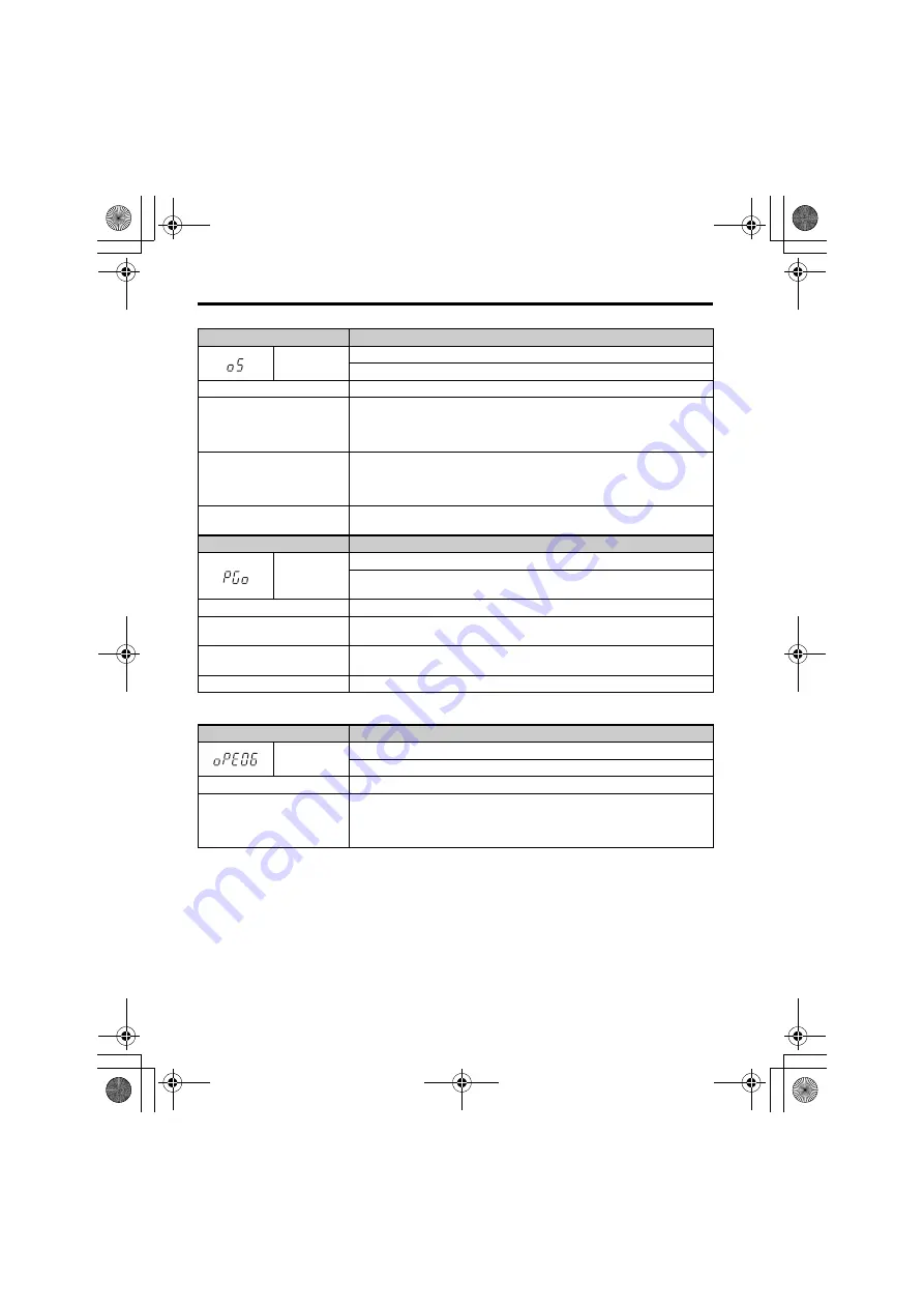
Table 12  Operation Error Displays, Causes, and Possible Solutions

Keypad Display

Fault Name

oS

Overspeed
The motor speed feedback exceeded the F1-08 setting.

Cause

Possible Solution

Overshoot is occurring.

• Increase the settings for C5-01 (Speed Control Proportional Gain 1) and reduce 

C5-02 (Speed Control Integral Time 1).

• Adjust the input signal using parameters H6-02 through H6-05.
• Enable Feed Forward Control and perform Inertia Auto-Tuning in CLV.

Incorrect speed feedback scaling 
when terminal RP is used as 
speed feedback input in V/f 
control.

Set H6-02 to the value of the speed feedback signal frequency when the motor 
runs at the maximum speed.

Inappropriate parameter settings.

Check the setting for the overspeed detection level and the overspeed detection 
time (F1-08 and F1-09).

Keypad Display

 Fault Name

PGo

PG Encoder Disconnected
The drive has not received a PG encoder pulse for longer than the time set in 
F1-14.

Cause

Possible Solution

The PG encoder is disconnected 
or is not wired properly.

Make sure the PG encoder is properly wired or is not disconnected.

PG encoder does not have 
enough power.

Confirm that the correct power supply is properly connected to the PG encoder.

Motor brake is engaged.

Ensure the brake releases properly.

Keypad Display

Fault Name

oPE06

Control Method Selection Error
Correct the setting for the control method.

Cause

Possible Solution

Control method requires 
installing a PG option, but no PG 
option is installed (A1-02 = 1, 3, 
or 7).

• Connect a PG option.
• Correct the value set to A1-02.

TOBP_C730600_75B_1_0_E.book  40 ページ  2017年2月17日 金曜日 午後3時2分

Summary of Contents for pg-b3

Page 1: ...n Manual Type PG B3 To properly use the product read this manual thoroughly and retain for easy reference inspection and maintenance Ensure the end user receives this manual COSMOS 140 182 CI MANUAL N...

Page 2: ...en permission of Yaskawa No patent liability is assumed with respect to the use of the information contained herein Moreover because Yaskawa is constantly striving to improve its high quality products...

Page 3: ...stallation Manual 3 Table of Contents 1 PREFACE AND SAFETY 4 2 PRODUCT OVERVIEW 8 3 RECEIVING 9 4 OPTION COMPONENTS 10 5 INSTALLATION PROCEDURE 11 6 RELATED PARAMETERS 35 7 TROUBLESHOOTING 38 8 EUROPE...

Page 4: ...to the end user YASKAWA offers an express warranty only as to the quality of its products in conforming to standards and specifications published in the manual NO OTHER WARRANTY EXPRESS OR IMPLIED IS...

Page 5: ...L1000A Series Drive YASKAWA U1000 Series Drive YASKAWA U1000L Series Drive YASKAWA AC Drive GA700 YASKAWA AC Drive CR700 YASKAWA AC Drive CH700 YASKAWA AC Drive 1000 Series A1000 L1000A U1000 U1000L...

Page 6: ...cate safety messages in this manual Failure to heed these messages could cause fatal injury or damage products and related equipment and systems DANGER Indicates a hazardous situation which if not avo...

Page 7: ...the manual number shown on the front cove to order new copies of the manual DANGER Heed the safety messages in this manual Failure to comply will cause death or serious injury The operating company i...

Page 8: ...drive to compensate for subtle variations in the load while providing the drive with the necessary data to control the output frequency and maintain an accurate constant speed The option reads a 50 kH...

Page 9: ...1 on page 10 for details Contact the distributor where the option was purchased or the Yaskawa sales office immediately about any problems with the option u Option Package Contents u Installation Too...

Page 10: ...ils on TB1 and TB2 terminal functions and signal levels A Connector CN5 D Ground terminal FE and installation hole 1 1 Connect the provided ground wires during installation Installation to GA700 CR700...

Page 11: ...nsafe voltages to confirm the drive is safe WARNING Electrical Shock Hazard Do not operate equipment with covers removed Failure to comply could cause death or serious injury The diagrams in this sect...

Page 12: ...ge to circuitry Never connect or disconnect the motor from the drive while the drive is outputting voltage Improper equipment sequencing could damage the drive Do not connect or operate any equipment...

Page 13: ...ding on the drive model Refer to Table 2 to check the procedures for installing and wiring options on a drive Table 2 Procedures for Installing and Wiring Options on a Drive Drive Series Procedures fo...

Page 14: ...l packaged with the drive 2 Verify that the drive functions normally Refer to Figure 2 for an exploded view of the drive with the option and related components for reference in the installation proced...

Page 15: ...arning label The internal capacitor remains charged even after the drive is de energized The charge indicator LED will extinguish when the DC bus voltage is below 50 Vdc When all indicators are OFF me...

Page 16: ...K or CN5 C L connector on the drive and fasten it into place using the included screws C Tighten both screws to 0 5 to 0 6 N m 4 4 to 5 3 in lbs Use the CN5 C connector L when connecting only one opt...

Page 17: ...ation hole on the option B using the last remaining provided screw C Figure 5 Figure 5 Connect the Ground Wire Note 1 The option package includes two ground wires Use the longer wire to connect the op...

Page 18: ...e may be required to ensure that cable shielding does not contact other wiring Insufficient insulation may cause a short circuit and damage the option or drive Figure 6 Figure 6 Prepare Ends of Shield...

Page 19: ...r type Control Method Number of PG Encoders F1 21 Setting F1 37 Setting Single Pulse A V f w PG 1 0 N A 2 N A 0 CLV 1 N A N A 2 N A N A Two Pulse AB Quadrature V f w PG 1 1 N A 2 N A 1 CLV 1 None Requ...

Page 20: ...the perforated tabs on the left side of the front cover as shown in Figure 8 A to create the necessary openings on these models Refer to the Peripheral Devices Options section of the drive instruction...

Page 21: ...the front covers of the drive D F and replace the digital operator E NOTICE Do not pinch cables between the front covers and the drive Failure to comply could cause erroneous operation Figure 9 Figure...

Page 22: ...udden Movement Hazard Lock out the Run circuit to prevent issuing a Run command prior to manually rotating the motor shaft with the drive energized Failure to comply could cause death or serious injur...

Page 23: ...ve terminals according to the manual packaged with the drive 2 Verify that the drive functions normally Refer to Figure 12 for an exploded view of the drive with the option and related components for...

Page 24: ...ltages to confirm the drive is safe 1 Shut off power to the drive wait the appropriate amount of time for voltage to dissipate confirm all charge indicator LEDs extinguish then remove the front cover...

Page 25: ...e using the temporary placement holes Refer to the manual packaged with the drive for details on removing the LED Status Ring board NOTICE Do not remove the LED Status Ring board cable connector Failu...

Page 26: ...ng two options Note Installing the option card on a GA700 CR700 and CH700 drive requires only two screws and does not require a ground wire The option package ships with three screws and ground wires...

Page 27: ...g F1 37 Setting Single Pulse A V f w PG 1 0 N A 2 N A 0 CLV 1 N A N A 2 N A N A Two Pulse AB Quadrature V f w PG 1 1 N A 2 N A 1 CLV 1 None Required None Required 2 None Required None Required Two Pul...

Page 28: ...F and the front cover of the drive D including the keypad E Figure 18 Figure 18 Replace the LED Status Ring Board Front Cover and Keypad F D E Install the keypad to the drive after replacing the keypa...

Page 29: ...side the LED Status Ring board to route option wiring when using connector CN5 B NOTICE Do not pinch cables between the front cover or the LED Status Ring board and the drive Failure to comply could c...

Page 30: ...den Movement Hazard Lock out the Run circuit to prevent issuing a Run command prior to manually rotating the motor shaft with the drive energized Failure to comply could cause death or serious injury...

Page 31: ...included ground wires between the option FE terminal and the drive ground terminal connected to earth ground for 1000 Series installation Fasten the option FE terminal in the ground plate using one of...

Page 32: ...ds do not extend from the crimp terminals Table 6 Crimp Terminal Sizes Terminal Signal Screw Size Tightening Torque N m in lb Bare Cable Crimp Terminals Wire Type Recomm Gauge mm2 Applicable Gauges mm...

Page 33: ...l Functions on page 34 Figure 21 Figure 22 Wiring PG Encoder Cable Table 7 Connecting the PG Encoder Cable Specification Table 8 PG Encoder Cable Types Option Terminal PG Encoder Cable Wire Color Pin...

Page 34: ...8 to 12 V L level 2 0 V or less A A inverse pulse input B B pulse signal input B B inverse pulse input Z Z pulse signal input Z Z inverse pulse input SD NC pin open For use when cables shields should...

Page 35: ...w PG CLV AOLV Default 1 Min 1 Max 1 F1 02 381 PG Feedback Loss Selection Selects the stopping method after PG disconnect PGo 0 Ramp to stop 1 Coast to stop 2 Fast Stop Use C1 09 3 Alarm only 4 No ala...

Page 36: ...efault 10 Min 0 Max 50 F1 11 38A Speed Deviation Detect Delay Time Sets the time required for a speed deviation situation to trigger a fault V f w PG CLV AOLV Default 0 5 Min 0 0 Max 10 0 F1 12 38B 3...

Page 37: ...pulses are set as 1 32 1 V f w PG CLV Default 1 Min 1 Max 132 F1 37 3BD 7 PG 2 Signal Selection 0 A pulse detection 1 AB pulse detection V f w PG Default 0 Range 0 1 1 Varies by drive model 2 Use the...

Page 38: ...n the setting in F1 10 for longer than the time set to F1 11 Cause Possible Solution The load is too heavy Reduce the load The acceleration and deceleration times are set too short Increase the accele...

Page 39: ...on is connected to drive port CN5 A Cause Possible Solution Non compatible option is connected to drive port CN5 A Use only compatible options The PG option cannot be connected to CN5 A For other opti...

Page 40: ...runs at the maximum speed Inappropriate parameter settings Check the setting for the overspeed detection level and the overspeed detection time F1 08 and F1 09 Keypad Display Fault Name PGo PG Encoder...

Page 41: ...d the shield of the cable on the PG encoder side and the drive side 5 Verify that the shield is properly grounded and ground one end of the signal line or remove the ground connection on both ends if...

Page 42: ...drives displaying the CE mark in combination with other devices it is ultimately the responsibility of the user to ensure compliance with CE standards Verify that conditions meet European standards af...

Page 43: ...SI Figure 26 Figure 27 Option Installation for CE Compliance A Braided shield cable C Cable clamp conductive B Metal panel C B A L1 L2 L3 L1 L2 L3 R CN5 B CN5 C CN5 A CN5 B CN5 C CN5 A S T PG Drive E...

Page 44: ...ible Control Modes V f w PG CLV AOLV Maximum Input Frequency 50 kHz Pulse Monitor Output Monitor for A B and Z pulse output 24 V max 30 mA Open collector output Pulse Monitor Wiring Length 30 m 98 ft...

Page 45: ...back cover Date of Publication Rev No Section Revised Content September 2017 2 Back cover Revision Address February 2017 1 All Addition Applicable drive series Revision Reviewed and corrected entire d...

Page 46: ...0099 Fax 66 2 017 0799 http www yaskawa co th YASKAWA ELECTRIC CHINA CO LTD 22F One Corporate Avenue No 222 Hubin Road Shanghai 200021 China Phone 86 21 5385 2200 Fax 86 21 5385 3299 http www yaskawa...

Reviews: