


Internal cables and compressed air lines
8
-
44
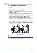
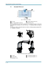
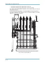
Fig. 8-2: Field bus cable connection
2. As shown in Fig. 8-2: "Field bus cable connection", the tube for field bus cable (inner diameters: 12 mm), will
beconnected by connecting the section with the S-head. Lead the field bus cable C as described below.
Wire harness
Pipe for the field bus cable (Ø12)
Connection
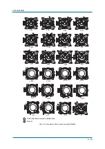
Step 1: pipe for the field bus cable (inner diameter 12 mm) 12 mm) will
be connected over a connection, inthere the cable
is lead.
Step 2:
Remove the connection from the field bus cable pipe.
Pull the field bus cable
, fastened at the cable
is, until it gains
the connection.
Step 4:
Separate the cable
from field bus cable
, by cutting off.
Step 5:
Remove the connection, fasten cable
at the field bus cable
and then lead it through the robot
Cable A
Field bus cable C
Connection
Section
Pipe for the field bus cable (Ø12)
1
2
3
1
3
2
1
3
2
A
C
4
5
4
C
A
C
A
A
C
A
C
1
4
2
5
3
Summary of Contents for MPL500-J00
Page 1: ...ROBOTICS MPL500 J00 YR MPL0500 J00 Operating and Maintenance Manual ...
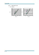
Page 36: ...Technical data 6 36 6 5 1 2 Stop position L axis 100 deflection ...
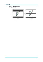
Page 37: ...Technical data 6 37 6 5 1 3 Stop position U axis 100 deflection ...
Page 61: ...Maintenance and inspection 9 61 Air outlet cap Joint 80 9 0 170 1 1 2 2 2 1 2 ...


