background image

Appendix E  Optional Functions

E.2  Security

A-90

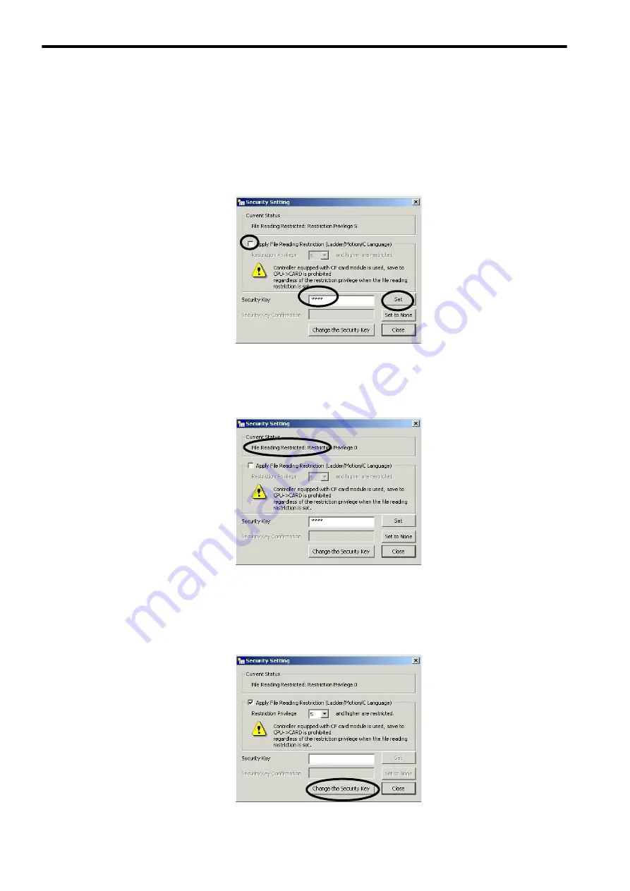
[ d ] Changing the File Reading Restriction

Change the file reading restriction with the security settings made. In this example, we will release the restriction. To 
set the restriction, use the same procedure. Having no file reading restriction set is the same as security being released. 

1.

Select or clear the 

Apply File Reading Restriction (Ladder/Motion/C Language)

 Check Box. Enter 

the password in the 

Security Key

 Field, and then click the 

Set

 Button. 

2.

If the change in file reading restriction has been normally applied to the Controller, the status will 
change from 

File Reading Restricted

 to 

No Security Setting

 in the 

Current Status

 Area. 

[ e ] Changing the Security Key 

The security key can be changed with the security settings made. This procedure will change only the security settings. 

1.

Open the 

Security Setting

 Dialog Box, and then click the 

Change the Security Key

 Button. 

Summary of Contents for MP2200

Page 1: ...7F 01 EXIOIF 260F 01 YASKAWA MBU 03 CPU 01 MP2200 MBU 03 CPU 01 Overview Overview of Specifications and Functions Mounting and Wiring System Startup Overview of System Operation Built in Ethernet Comm...

Page 2: ...liability is assumed with respect to the use of the information contained herein Moreover because Yaskawa is constantly striving to improve its high quality products the information contained in this...

Page 3: ...rs of this manual as required by the purpose For information on how to use motion parameters and motion commands refer to Machine Controller MP2000 series Built in SVB SVB 01 Motion Module User s Manu...

Page 4: ...to an MP2000 series Machine Control ler Machine Controller MP2000 Series 263IF 01 EtherNet IP Communication Module User s Manual SIEP C800700 39 Describes the specifications and communication methods...

Page 5: ...itor which assists MP900 MP2000 series design and maintenance Machine Controller MP900 MP2000 Series New Ladder Editor User s Manual Operation SIEZ C887 13 2 Describes the operating methods of the New...

Page 6: ...tions that if not heeded could possibly result in loss of life serious inju ry or property damage Indicates precautions that if not heeded could result in relatively serious or minor injury or propert...

Page 7: ...achine or even cause acci dents resulting in injury or death There is a risk of electrical shock Do not remove the front cover cables connector or options while power is being supplied There is a risk...

Page 8: ...e the product is packaged and methods other than fumigation must be used Example Heat treatment where materials are kiln dried to a core temperature of 56 C for 30 minutes or more If the electronic pr...

Page 9: ...olarity correctly There is a risk of battery damage or explosion Do not allow the battery to be replaced by anyone other than qualified personnel who have received safety training Improper battery rep...

Page 10: ...nto the Controller After replacing the battery dispose of the old battery separate from regular waste and in accordance with local regulations Observe the following general precautions to ensure safe...

Page 11: ...product in a manner in which it was not originally intended 5 Causes that were not foreseeable with the scientific and technological understanding at the time of shipment from Yaskawa 6 Events for whi...

Page 12: ...operty Systems that require a high degree of reliability such as systems that supply gas water or electricity or sys tems that operate continuously 24 hours a day Other systems that require a similar...

Page 13: ...1 1 General Specifications 2 3 2 1 2 Product Specifications 2 4 2 1 3 Function Lists 2 5 2 2 Base Unit 2 6 2 2 1 Overview of Functions 2 6 2 2 2 LED Indicators 2 6 2 2 3 Hardware Specifications 2 8 2...

Page 14: ...d Wiring 3 1 3 1 Mounting MP2200 3 2 3 1 1 Method 3 2 3 1 2 MP2200 Mount Direction 3 5 3 1 3 Installation Clearance 3 6 3 1 4 Replacing and Adding Optional Modules 3 7 3 2 Connecting Basic Units 3 10...

Page 15: ...6 Built in Ethernet Communication Supported by the CPU 03 and CPU 04 6 1 6 1 Communication Methods 6 2 6 2 Communication with Other MP Series 6 3 6 2 1 When the CPU 03 CPU 04 Acts as Slave automatic...

Page 16: ...28 8 2 6 List of Causes for Command Error Completed Status 8 32 8 2 7 Troubleshooting Motion Errors 8 35 Appendices Appendix A System Registers Lists A 2 A 1 System Service Registers A 2 A 2 Scan Exe...

Page 17: ...P2200 Modules 1 4 1 3 System Configuration 1 6 1 3 1 Example 1 6 1 3 2 System Configuration Precautions 1 9 1 4 Devices Connectable to MECHATROLINK 1 10 1 4 1 Devices Connectable to MECHATROLINK I II...

Page 18: ...MECHATROLINK II baud rate 2 5 times faster than MP920 previous model CPU processing speed 2 0 to 5 0 times faster than MP920 previous model Larger user memory area High speed 0 5 ms motion control is...

Page 19: ...Appearance 1 3 1 Overview 1 2 MP2200 Configuration 1 2 1 Basic Unit Appearance The appearance of the Basic Units is shown below MP2200 MBU 01 POWER CPU 01 SVB 01 218F 01 LIO 02 LIO 01 LIO 01 217F 01 E...

Page 20: ...U2210 E JEPMC BU2210 24 VDC 20 9 slots Base Unit for DC power supply MBU 03 JEPMC BU2220 E 24 VDC 20 4 slots CPU Modules CPU Modules CPU 01 JAPMC CP2200 E JAPMC CP2200 CPU Module for MP2200 system CPU...

Page 21: ...Analog input 4 channels Counter Module CNTR 01 JAPMC PL2300 E Reversible counter 2 channels Communica tion Modules Ethernet Communica tion Module 218IF 01 JAPMC CM2300 E JAPMC CM2300 RS 232C and Ether...

Page 22: ...ions including I O Max 16 stations servo can be included Host PLC Inverter Servo Servo Servo Repeater Terminating resistor 130 24 VDC Optional Modules 266IF 02 217IF 01 218IF 01 218IF 02 260IF 01 261I...

Page 23: ...cted to MECHATROLINK I 4 Mbps and MECHATROLINK II 10 Mbps Refer to 1 4 1 Devices Connectable to MECHATROLINK I II and select the appropriate SERVOPACKs 4 If devices compatible with MECHATROLINK I and...

Page 24: ...218F 01 LIO 02 LIO 01 LIO 01 217F 01 EXIOIF 260F 01 Y ASKA LIO 01 LIO 0 2 LIO 0 4 LIO 0 5 DO 01 AI 01 AO 01 LIO 0 6 215AIF 01 216AIF 01 217IF 01 218IF 01 260IF 01 261IF 01 SVA 01 SVB 01 PO 01 Motion c...

Page 25: ...ecommended by Yaskawa Yaskawa has a range of cables Always check the device to be used and select the correct cable for the device Different SERVOPACKs are connected to MECHATROLINK I and MECHATROLINK...

Page 26: ...Application Module Yes No SGDH E JUSP NS115 II Series SGDH SERVOPACK NS115 MECHATROLINK II Application Module Yes Yes SGDS 1 III Series SGDS SERVOPACK Yes Yes SGDX 12 SGDX SERVOPACK Yes Yes SJDE AN SJ...

Page 27: ...Output Module Pulse output 2 channels Yes No JAMSC IO2900 E DC Input Module 12 24 VDC 16 inputs Yes Yes JAMSC IO2910 E DC Output Module 12 24 VDC 16 outputs Yes Yes JAMSC IO2920 E 8 point I O Module 2...

Page 28: ...0 SGD7S SERVOPACKs with MECHATROLINK III Communications Refer ences Model Number Details CIMR A SI ET3 High Performance Vector Control Drive A1000 MECHATROLINK III Option Card CIMR V SI ET3 V Compact...

Page 29: ...rite core Used between the following devices SVC 01 and SGDV 21 SVC 01 and SGDV 25 JEPMC W6013 E with MECHATROLINK III connectors on both ends with ferrite core JEPMC W6014 E with loose wires on one e...

Page 30: ...onnector MSTB2 5 5 GF 5 08AU manufactured by Phoenix Contact 261IF 01 PROFIBUS PROFIBUS communication cable Module side connector 17LE 13090 27 D33C manufactured by DDK Ltd 262IF 01 FL net Ethernet co...

Page 31: ...Japan Ltd black 721 203 026 000 MBU 02 MBU 03 Unit Cable side manufactured by WAGO Company of Japan Ltd white DIN Rail Mounting Parts Optional JEPMC OP300 1 pair Cover for Option Slot Optional JEPMC...

Page 32: ...9 2 3 2 LED Indicators and Switch Settings 2 9 2 3 3 Hardware Specifications 2 11 2 3 4 SVR Module Virtual Motion Module 2 12 2 4 CPU 02 Module 2 15 2 4 1 Overview of Functions 2 15 2 4 2 External App...

Page 33: ...Module 2 71 2 6 5 218IFC Module Ethernet 2 72 2 6 6 M EXECUTOR Module Motion Program Executor 2 75 2 7 EXIOIF Module 2 76 2 7 1 Overview of Functions 2 76 2 7 2 External Appearance 2 76 2 7 3 Hardware...

Page 34: ...or corrosive gas Operating Altitude 2 000 m above sea level or lower Mechanical Operating Conditions Vibration Resistance Conforming to JIS B 3502 10 to 57 Hz with single amplitude of 0 075 mm 57 to...

Page 35: ...when sixteen SVB 01 Modules are added Number of Virtual Axis Controlling Axes 16 axes CPU Processing Speed Comparison 1 0 1 0 1 6 2 5 Scan Interval Setting High speed Scan 0 5 ms to 32 ms per 0 5 ms...

Page 36: ...ams Data Memory Common data M registers System S registers Drawing local D registers Drawing constant registers Input I registers Output O registers Constant C registers 64 kwords 8 kwords Up to 16 kw...

Page 37: ...des either four option slots short rack or nine option slots Any Optional Modules can be mounted in the option slots to create the perfect system for the machinery 2 2 2 LED Indicators 1 External Appe...

Page 38: ...r Supply Short Rack 2 Indicator The LED indicator that displays the status of the power supply is detailed in the following table The short rack Base Unit does not have a POWER indicator MP2200 MBU 03...

Page 39: ...ncluding slots for Expansion Modules Optional Expansion Rack Rack 2 3 4 Configuration 9 slots for Optional Modules because a CPU Module is not mounted to Racks 2 3 and 4 Basic Unit Rack Rack 1 Configu...

Page 40: ...the CPU 01 Module 2 Indicators The LED indicators that display the operating status and error details for the Base Unit are detailed in the follow ing table Note Refer to 8 2 3 2 LED Indicator Meaning...

Page 41: ...OFF User program running 5 SUP ON System use OFF Always set to OFF OFF Normal operation 4 INIT ON Memory clear OFF Set to ON to clear the memory If this switch is set to OFF the program stored in flas...

Page 42: ...of the CPU 01 Module Item Specifications Name CPU 01 Module Model JAPMC CP2200 Abbreviation CPU 01 Flash Memory 12 MB SDRAM 32 MB SRAM 512 KB M registers S registers trace memory alarm history battery...

Page 43: ...rs and can be accessed from application programs using I O registers The SVR can be used to control up to 16 virtual axes in the high speed scan control cycle Note For information on how to use SVR mo...

Page 44: ...axis for phase control Electronic cam or shaft operation can be achieved by using the SVR for the virtual master axis 2 Multi axis synchronous con trol Multi axis synchronous control can be achieved b...

Page 45: ...s The number of axes 1 to 16 when Selection of Operation Modes fixed parameter 0 is set to Normal Operation Mode 0 The formula listed above do not apply when the number of axes is 0 Differences from S...

Page 46: ...through the MPE720 to save them as a batch Also applications can be loaded from the Compact Flash directly to the CPU in batch loads The USB connector has only one channel which works as a port only...

Page 47: ...ng the Compact Flash BAT Red Battery alarm activated 1 LED2 TRX Green Communicating with USB 2 STS Red Lights or blinks for errors 2 LED3 On the side of the Compact Flash connector lever PWON Green Su...

Page 48: ...tch load from the Compact Flash Compact Flash CPU OFF Enabled when switches SW2 4 is ON Com pact Flash enabled With the LOAD switch set to ON a batch load from the Compact Flash is executed when the p...

Page 49: ...tions Name CPU 02 Module Model JAPMC CP2210 Abbreviation CPU 02 Flash Memory 16 MB User s area 11 5 MB SDRAM 32 MB SRAM 2 MB M registers S registers trace memory alarm history battery backup External...

Page 50: ...in the following table is recommended Media Memory Capacity 32 MB 64 MB 128 MB 256MB 512MB For Partition Not available Applicable FAT FAT12 16 32 VFAT long name Up to 256 characters of a file name ar...

Page 51: ...tus SW00654 SB006540 0 Compact Flash card not mounted 1 Compact Flash card mounted SB006541 0 Power not supplied 1 Power being supplied SB006542 0 Compact Flash card not identified 1 Compact Flash car...

Page 52: ...e accessing the Compact Flash with the CARD LED indicator lamp lit the FAT in the Compact Flash may be damaged The CPU 02 Module checks the FAT when the switch SW2 4 CARD is set to ON and attempts to...

Page 53: ...ndicator lamp will light up 4 Set the SAVE switch to ON The batch save will start and the CARD LED indicator lamp will light up When a batch save is completed the CARD LED indicator lamp will go out N...

Page 54: ...icator lamp will light up and the batch load will start The CARD LED indicator lamp will light up and the RUN LED indicator lamp will blink When all of the data has been successfully read out from the...

Page 55: ...ecifications The following table describes the general specifications of the USB interface CPU 02 Module 1 CPU 02 Module 2 CPU 02 Module N USB cable USB hub USB cable USB cable USB cable Personal Comp...

Page 56: ...urn ON the MP2200 power supply 2 A message Find New Hardware will be displayed Then Found New Hardware Wizard will be dis played Click the Next button Classification Indicator Name Indicator Details D...

Page 57: ...this device so that I can choose a specific driver and click the Next button A message will appear asking where to find the driver 4 Insert the MPE720 setup disc into the CD ROM drive 5 Select CD ROM...

Page 58: ...power supply connected to a USB perform the following operations to safely undo the connections 1 In the task tray at the lower right of the window click the icon to remove the device A message Stop U...

Page 59: ...Button Creating the new file will be canceled and editing will continue 2 Open the folder at the save location input the file name and select the file type and machine controller to be used The setti...

Page 60: ...nnection Button and Setting Button will be dis abled and it will not be possible to set communications The operation of MPE720 version 6 when connected to the Machine Controller is different depending...

Page 61: ...les from the USB hub Note Refer to 2 4 6 5 Removing the Cable from the USB Connector 3 After turning ON the USB1 switch SW2 of the CPU 02 Modules where the local station is to be set use the USB cable...

Page 62: ...ommunication settings will be completed and the system will be connected online 8 Double click the Module configuration Icon in the System Subwindow to display the window for mod ule configuration def...

Page 63: ...CPU 02 Module 11 Flash store the data and log off after returning to the MPE720 Ver 6 Window 12 Turn OFF the USB1 switch SW2 of the CPU 02 Module and then turn the power supply of the MP2200 OFF and...

Page 64: ...Module from the Compact Flash i e batch loaded Standard feature Ethernet 100 Mbps High speed communication can be performed with the MPE720 Engineering Tool Communication can be performed with a touch...

Page 65: ...rs Ethernet Connector LED1 indicators SW1 switch LED2 indicators SW2 switch Compact Flash CF slot LED3 indicator Indicators Indicator Name Color Significance when Lit LED1 RDY Green Unit operating nor...

Page 66: ...opped OFF Stops the user program execution Enabled only when debugging OFF User program running 5 SUP ON System use OFF Always set to OFF OFF Normal operation 4 INIT ON Memory clear OFF Set to ON to c...

Page 67: ...s SW2 4 is ON Com pact Flash enabled With the LOAD switch set to ON a batch load from the Compact Flash is executed when the power supply is turned ON OFF Batch load is not executed 2 SAVE OFF ON Save...

Page 68: ...ARD Module Item Specifications Name CPU 03 Module Model JAPMC CP2220 E Abbreviation CPU 03 Flash Memory 16 MB User s area 11 5 MB DDR 64 MB SRAM 4 MB 3 MB max with battery backup can be used for table...

Page 69: ...otocol A compatible I E frame Support for MODBUS TCP protocol Support for non procedure communication An I O message communication function enables you the data exchange in the form of I O image when...

Page 70: ...ems Description Communication Interface 1 10Base T 100Base TX Communication Protocol 2 TCP UDP IP ARP ICMP Maximum Number of Communication Connections 4 2 I O Message communication Maximum Number of C...

Page 71: ...n protocol of the 218IFA is used either a single buffer or multiple buffers can be selected for the receive buffers in the 218IFA If multiple buffers are selected 20 data items per connection can be p...

Page 72: ...k it to open the 218IFA detailed definition window Module Type A module name is shown Changing the name to UNDEFINED enables you to disable 218IFA functions Circuit Number Module s line number valid r...

Page 73: ...Window a Displaying the 218IFA Module Detailed Definition Window Select CPU 03 in the Controller Area of the Module Configuration Window and then double click the Slot Number cell for the 218IFA Modu...

Page 74: ...Module Detailed Definition Window The 218IFA Module detailed definition window is composed of Transmission Parameter and Status Tabs and each tab is changed with a click 1 Transmission Parameters Tab...

Page 75: ...Ad dress router IP ad dress 0 0 0 0 to 255 255 255 254 Sets the 218IFA default gateway IP address However the follow ing addresses are excluded 127 xxx xxx xxx xxx xxx xxx 000 except 000 000 000 000 x...

Page 76: ...ommunication process The port number cannot be 9998 or 10000 9999 Response Time 0 to 255 sec Specify the wait time until a remote response is returned after sending a command when carrying out a messa...

Page 77: ...e IP Address 0 0 0 0 to 255 255 255 254 Set the remote IP address for each connection However the fol lowing addresses are excluded 127 xxx xxx xxx xxx xxx xxx 000 except 000 000 000 000 xxx xxx xxx 2...

Page 78: ...cted as fol lows Available Not available ASCII Detail Automatically Receive Opens the Detail setting Dialog Box To open the dialog box dou ble click this button Note The automatic receive function is...

Page 79: ...box is opened Note For the 218IFC of the CPU 04 the setting range for the connection number is larger i e 1 to 20 By clicking the Default Button default values are set for each data code type accordin...

Page 80: ...channel is associated with the connec tion according to the input item CH NO for the MSG SND MSG RCV function and node connection number PARAM02 setting for the parameter list PARAM When automatic re...

Page 81: ...ion protocol type Note Enable Disable Setting Item Communication Protocol Type Extended MEMOBUS MEMOBUS MELSEC Non proce dure MODBUS TCP Readout of Input Relay Readout of Input Register Readout Write...

Page 82: ...lished L Scan Read Write In 218IFA Ethernet communications remote stations are distin guished by their connection numbers I O message communications have a connection for each read write Local Port 25...

Page 83: ...indow OW 4 Note2 Data Size Varies according to protocol type Specify the data size word read from the remote device 4 Specify the data size word written in the remote device 4 Head Register Number for...

Page 84: ...n Parameter are not yet set and this dialog box is opened Item Default MP Series Local Port IP Address Values set in Transmission Parameter setting items are shown Local Port Number Read 10005 Write 1...

Page 85: ...hese default values Communication Protocol Type Default Data Code Type Local Input Output Register Setting Read Write Size Node Read Write Register Setting Extended MEMOBUS BIN IW to IW 3 input OW 4 t...

Page 86: ...s Tab 000 000 000 000 Engineering Port Displays a port number set in the detailed definition of the Transmission Parame ters Tab 9999 Item Displayed Content Default Trans Transmission Status Displays...

Page 87: ...the MSG SND func tion but the connection was rejected by the remote station and the command was reset When disconnecting the cable retried con necting for one minute default value with out a response...

Page 88: ...he ladder program Note You can incorporate a MSEE command into the ladder program as ever Controlling a motion program without using a ladder program You can map any register to the control signal of...

Page 89: ...Sequential Execution Startup Event driven H Scan Scan execution L Scan Scan execution System Work 1 1 correspondence between the definition number and system work The number of program definitions is...

Page 90: ...vailable Item Description Change Slot Number Sub slot number Double click to open the M EXECUTOR detailed definition window Module Type A module name appears Changing the name to UNDEFINED enables you...

Page 91: ...Register M EXECUTOR Input Register Item M EXECUTOR Output Register Item IW 0 Definition No 1 Status OW 0 Definition No 1 Program number IW 1 Spare OW 1 Control signal IW 2 Spare OW 2 Override IW 3 Sp...

Page 92: ...are executed according to the scan in ascending numeric order A white cell can be set by the user and a grey cell cannot be set by the user Individual display Display the Program execution registry s...

Page 93: ...xecuted each high speed scan Motion Program Motion program Turns ON the program operation start request of the control signal runs when the program operation start request is ON Designa tion Method Mo...

Page 94: ...m and monitors the state using the M EXECUTOR control register Note For details on the M EXECUTOR control register refer to items 4 and 5 under 5 2 3 Motion Programs Allocation Disable Enables disable...

Page 95: ...ocation register and M EXECUTOR control registers Any register bit can be mapped to the allocation contact interlock Caution An allocation contact interlock is used to interlock the operation of a mot...

Page 96: ...e and the Allocation Control Regis ter Tab Page Program execution registry number Selects a program execution registration No Program number Sets a program number Execution type Sets the program execu...

Page 97: ...r process Drawing A startup process drawing Per high speed scan interval Batch output Batch input Batch output Batch input Drawing H high speed scan process drawing Per low speed scan interval Drawing...

Page 98: ...ling The following diagram shows the execution scheduling when set in the tab page above SPM003 MPM004 SPM005 DWG H SPM001 DWG A DWG L SPM003 MPM004 SPM002 SPM005 DWG H DWG X SPM002 High speed scan cy...

Page 99: ...rformed with a touch panel without using ladder programming automatic recep tion Communication can be performed with the host PLC without using ladder programming I O message com munication Simple Pro...

Page 100: ...to 8 2 3 2 LED Indicator Meanings on the meaning of indicators Ethernet connector LED1 indicators SW1 switch LED2 indicators SW2 switch Indicators Indicator Name Color Significance when Lit LED1 RDY...

Page 101: ...the memory Also set to ON not to save the data in the Compact Flash If this switch is set to OFF the program stored in flash memory will be executed OFF Normal operation 3 CNFG ON Configuration mode O...

Page 102: ...2 3 4 SVR Module Virtual Motion Module Item Specifications Name CPU 04 Module Model JAPMC CP2230 E Abbreviation CPU 04 Flash Memory 16 MB User s area 11 5 MB DDR 64 MB SRAM 4 MB 3 MB max with battery...

Page 103: ...mes QnA compatible 3E frames Support for MODBUS TCP protocol Support for OMRON protocol Support for non procedure communication An I O message communication function enables you the data exchange in t...

Page 104: ...ARP ICMP Maximum Number of Communication Connections 20 2 I O Message communication Maximum Number of Communication Channels 10 2 I O Message communication Message Communication maximum MEMOBUS Write...

Page 105: ...FC is used either a single buffer or multiple buffers can be selected for the receive buffers in the 218IFC If multiple buffers are selected 20 data items per connection can be processed at the same t...

Page 106: ...e Configuration Definition The following window shows the module configuration for the CPU 04 4 218IFC Module Detailed Definition Window Refer to 2 5 6 2 Specification of 218IFA Module For the 218IFC...

Page 107: ...or External output connector Item Specifications Abbreviation EXIOIF Model JAPMC EX2200 Function Expansion rack interface maximum 4 Rack configuration Expansion Bus Connector HDRA EC68LFDT SL HONDA Ex...

Page 108: ...l Also complex mechanical operation can be achieved by changing the control mode during axis operation Features Control performed in a shorter cycle but for the same maximum num ber of axes as with ME...

Page 109: ...PORT or 10Base T connector Machine Controller MP2 00 Communication Module User s Manual manual no SIEP C880700 04 218IF 02 Module Equipped with serial interface RS 232C and Ethernet interface Allows y...

Page 110: ...tor Models MBU 01 721 203 026 304 Black MBU 02 721 203 026 000 White 2 Attachment Handle for power connector model 231 131 These handles are used when connecting a cable to the cable end connector 4 5...

Page 111: ...odel 721 203 026 000 White 2 Attachment Handle for power connector model 231 131 These handles are used when connecting a cable to the cable end connector 4 5 130 121 4 5 18 108 120 111 4 5 4 5 111 0...

Page 112: ...r 2 81 2 Overview of Specifications and Functions 2 9 2 Mounting Procedure for EXIOIF Connector The EXIOIF Module has the following dimensions Height 125 mm Depth 95 mm The following figure shows the...

Page 113: ...3 2 3 1 1 Method 3 2 3 1 2 MP2200 Mount Direction 3 5 3 1 3 Installation Clearance 3 6 3 1 4 Replacing and Adding Optional Modules 3 7 3 2 Connecting Basic Units 3 10 3 2 1 Connecting Base Units 3 10...

Page 114: ...ap from the mounting base as shown in the following diagram If mounting a MP2200 using DIN rail with 10 mm gap install a spacer on the rear of the MP2200 near the bottom to protect the MP2200 from vib...

Page 115: ...n the rear of the MP2200 as shown in the following figure Note The following figure shows the front and back of a mounting clip Insert each clip so that its front faces outward 2 Pull the DIN rail mou...

Page 116: ...DIN rail mounting clips to lock them in place 5 Place end plates on both sides of the MP2200 to secure it to the DIN rail This completes the installation procedure 300 mm or less 300 mm or less C D MP...

Page 117: ...Direction 3 5 3 Mounting and Wiring 3 1 2 MP2200 Mount Direction Be sure to mount the MP2200 using screwed method or DIN rail MP2200 MBU 02 CPU 01 SVB 01 218F 01 CN1 CN2 BATTEY POWER DC PORT 10Base T...

Page 118: ...ng Conditions Above and below 50 mm min Left and right 50 mm min Note This clearance applies to an ambient temperature of 55 C max 50 mm min 50 mm min 50 mm min 50 mm min MP2200 MBU 02 CPU 01 SVB 01 2...

Page 119: ...bles from the MP2200 Then remove the MP2200 from the panel or rack and place on a workbench or other area with sufficient space 2 Removing Optional Modules 1 Remove the battery cover Pull the notch on...

Page 120: ...the Optional Module Hold the center of the battery cover as shown in the following diagram Push the battery cover down and out rotating from the round knob to disconnect the Module and mounting base...

Page 121: ...etely inserted place your hand on the front face of the Optional Mod ule and push hard until the Optional Module has been inserted into the mounting base connectors The front face of the Optional Modu...

Page 122: ...100 200 VAC to the MP2200 Connect the power supply connector as shown in the following diagram Name Connector Name No of Pins Connector Model Module Cable Manufacturer Cable Model Power Supply Connect...

Page 123: ...ollowing procedure to wire the terminal to the power supply connector Use 1 5 to 2 5 mm2 AWG16 to AWG13 twisted pair cable to connect the 100 200 VAC power supply to the power supply connector on the...

Page 124: ...power supply terminal has a removable connector Use the following procedure to wire the terminal to the power supply connector Use 0 8 to 2 6 mm2 AWG18 to AWG13 twisted pair cable to connect the 24 VD...

Page 125: ...g figure shows a connection example using multiple CPU 02 Modules Connector Specifications Name No of Pins Connector Model Module side Cable side Manufacturer CF slot 50 MI21A 50PD SF EJR 31 Hirose CF...

Page 126: ...able use a twisted pair cable with RJ 45 connector Name Connector Name Number of Pins Connector Model Module Side Cable Side Manufacturer Ethernet Ethernet 8 RJ 45 CAT5 Socket RJ 45 CAT5 Plug Pulse En...

Page 127: ...e HUB 100 m or less 100 m or less Cable Length between HUBs 100 m or less 100 m or less Number of HUBs between Nodes Up to four Unlimited HUB HUB 10Base T MP2200 MP2200 MBU 01 100 200V BATTEY POWER AC...

Page 128: ...ess Cable Length between HUBs 5 m or less 100 m or less Number of HUBs between Nodes Up to two Unlimited HUB HUB MPE720 MP2200 MP2200 MBU 01 Optional Module Optional Module 100 200V BATTEY POWER AC PO...

Page 129: ...other cable systems such as the main circuit or power lines 2 Communication system 100Base TX Communicate data to a remote device through TCP IP communication If necessary increase the number of commu...

Page 130: ...onnect the external I O connectors Note Attach the enclosed dust caps to the unused connectors 1 in the above figure These connectors are used to expand the number of mounting bases to a maximum of fo...

Page 131: ...nsion racks is 6 0 m max Connect the shield to the connector shell 2 Connection method 1 1 3 Cable specifications Shielded cable equivalent to UL20276 0 08 mm2 AWG28 two ferrite cores attached 3 Cable...

Page 132: ...SA SA R S T 1MCCB 24V O24V SGDS L1 L2 L1C L2C B1 B2 U V W C N 1 C N 3 C N 6 SGDS L1 L2 L1C L2C B1 B2 U V W C N 1 C N 3 C N 6 SGDS L1 L2 L1C L2C B1 B2 U V W C N 1 C N 3 C N 6 SGDS L1 L2 L1C L2C B1 B2 U...

Page 133: ...tartup Overview 4 2 4 2 Preparation 4 3 4 2 1 Wiring 4 3 4 2 2 Self Configuration 4 5 4 2 3 Test Operation 4 6 4 3 Programming 4 9 4 3 1 Creating a Project 4 9 4 3 2 Creating Group Definitions 4 10 4...

Page 134: ...em and to confirm the execution of motion program using the pro gram shown below The motion program created here is simple and has only three lines to move two axes 150 000 pulses from the current pos...

Page 135: ...Layout Model YASKAWA SERVOPACK 200V SGDS A5F12A SW1 CHARGE C N 3 A B C N 1 C N 2 C N 4 L1 L2 L2C L1C B1 B2 U V W C N 6 YASKAWA SERVOPACK 200V SGDS A5F12A SW1 CHARGE C N 3 A B C N 1 C N 2 C N 4 L1 L2...

Page 136: ...C880700 30 The SERVOPACK station number SW1 is set to 1 and 2 In a 1 1 connection without HUB use a cross cable as a LAN cable Product Name Model Q ty MP2200 Base Unit with AC power supply JEPMC BU22...

Page 137: ...pins on the DIP switch SW1 to ON on the MP2200 4 Turn ON the 100 VDC power supply to the MP2200 and confirm that the indicators change as follows 5 Self configuration is complete and MECHATROLINK slav...

Page 138: ...MPE720 Ver 6 Launch MPE720Ver 6 and click 3 Ethernet LP 192 168 1 1 to connect to the controller 2 Operating Manually in the Test Run Window When the connection is complete the display will change fr...

Page 139: ...Operation 4 7 4 System Startup 2 Axis Selection and Servo ON Set an axis number in the Axis Window and click the Enable Servo ON Button in the Test Run Window Turning the servo ON allows you to manip...

Page 140: ...e Icon and set a speed reference value and check that the axis rotates normally while the Forward Button or Reverse Button is pressed The operation check of the first axis is complete Press the Axis B...

Page 141: ...e personal computer desktop to start MPE720 version 6 2 Once MPE720 version 6 has started click New 3 Specify the file name location in which to save the file and Controller model and then click the C...

Page 142: ...k the Motion Tab in the subwindow to display Motion program in the subwindow 2 Right click Motion program in the left subwindow and then select Group Definition from the pop up menu 3 Click the OK But...

Page 143: ...gram and then click New in the pop up menu 2 Click the OK Button 3 Enter the motion program example given at the beginning of this section 4 Click the Icon in the Motion Editor to perform compiling On...

Page 144: ...at you created from DWG H by using an MSEE command For details refer to 5 2 3 2 How to Run a Motion Program 1 Click the Ladder Tab in the subwindow Ladder program will be displayed in the subwindow 2...

Page 145: ...Ready motion monitoring parameter IWxx00 bit 0 is ON and then turn ON the Servo ON Command MB000000 If Machine Controller Operation Ready is OFF the Servo ON Command will not be accepted Complement I...

Page 146: ...e MP2000 series Controller This procedure is not required if the motion program is made online 1 Click Communications Setting in the following window 2 Select the communications port that was set in 4...

Page 147: ...r is performed the same file in the Controller will be overwritten with the selected project file data If batch transfer is performed the RAM of the MP2000 series Controller will be cleared before tra...

Page 148: ...ster Set MB000000 to ON as shown in the following figure to turn ON the servo Complement The CPU 03 and CPU 04 turn ON the servo by directly using the motion setting parameters if the M EXECUTOR was u...

Page 149: ...wing procedure to save the data in the RAM in the MP2000 series Controller to the flash memory in the MP2000 series Controller 1 Click Transfer Save to flash in the following window 2 Click the Start...

Page 150: ...e Register List 1 Tab to display the register list Specify MB000000 for the register Set MB000000 to ON as shown in the following figure to turn ON the servo 2 Set MB000001 to ON as shown in the follo...

Page 151: ...ion Timing of User Program 5 6 5 2 2 Ladder Program 5 7 5 2 3 Motion Programs 5 12 5 2 4 Sequence Program Supported by CPU 03 and CPU 04 5 33 5 3 Registers 5 36 5 3 1 Types of Registers 5 36 5 3 2 Dat...

Page 152: ...Switch Name Status Operating Mode Default Setting Remarks S1 6 STOP ON User program stops OFF Set to ON to stop user program operation OFF User program operation S1 5 SUP ON System load OFF If set to...

Page 153: ...n High speed scan Interrupt signal Ladder program Power ON Startup self diagnostics 1 Memory clear FLASH RAM Copy Watchdog timer start DWG A executed Ladder program Order of priority High Low Online s...

Page 154: ...configuration 3 Operation Start When the STOP switch is set to OFF RUN the CPU will execute the ladder program in DWG A Refer to 5 2 2 Lad der Program for information on DWG A the startup processing d...

Page 155: ...Lit Lit Not lit Not lit Not lit User program executing normally Online operation mode Error Not lit Not lit Not lit Lit Not lit Major damage has occurred The ERR LED indicator is lit red when the CPU...

Page 156: ...m The following table shows the types and execution timing of MP2200 user program Sequence program is supported by the CPU 03 at CPU 04 For more information on the user program refer to the next page...

Page 157: ...ions are accessed and executed from parent child and grandchild drawings using the FUNC command a Drawing Types and Order of Priority Drawings are classified by their first letter A I H or L based on...

Page 158: ...Low speed scan processing is executed in spare processing time of the high speed scan Set the time of the high speed scan to approximately double the total execution time for DWG H Operation error Po...

Page 159: ...ld drawings are always called from parent drawings and grandchild drawings are always called from child drawings This is the hierarchical structure of drawings As shown in the following figure each pr...

Page 160: ...rawings by programming a DWG reference command SEE command in the parent and child drawings 2 Functions can be referenced from any drawing Functions can also be referenced from other functions 3 When...

Page 161: ...e maximum number of user functions that can be defined is 500 drawings Refer to the following manual for information on defining functions Machine Controller MP900 MP2000 Series User s Manual Ladder P...

Page 162: ...E of the leading word in the MSEE work registers 1 Groups A group of axes with related operations can be treated as one group by motion programs and programs can be executed for each group This allows...

Page 163: ...up operation Set it to 1 for the single group operation Set it to the number of group operation for the multiple group operation Group Name Define a group name Control Axis No Set the number of axes c...

Page 164: ...xis The axis number can be checked in the detailed window of the used motion module Logical Axis Name Define a name for the specified axis number The name defined here is used when programming a motio...

Page 165: ...fter the MSEE command is incorporated use a control signal to turn on the request for the program operation startup Motion programs are also called each scan cycle but unlike ladder programs all motio...

Page 166: ...rogram reg istration use a control signal to turn ON the request for the program operation startup The motion program registered in M EXECUTOR is executed at a scan cycle but similar to a ladder the w...

Page 167: ...ion program to call using a program number MPM Motion Program Referenced by a MSEE Command from a Ladder Program Set a program number to Program No in the MSEE command Fig 5 1 Calling a Motion Program...

Page 168: ...nd Fig 5 3 Calling a Motion Program Using an Indirect Designation 1 Motion Program Registered in M EXECUTOR Program Execution Definitions Supported by CPU 03 and CPU 04 Select Indirect for the Setting...

Page 169: ...ution is as follows Motion Program Registered in M EXECUTOR Program Execution Definitions Supported by CPU 03 and CPU 04 The work register is assigned to a M EXECUTOR control register automatically de...

Page 170: ...e motion program are stored in the error information win dow and S registers Bit No Status 0 Program running 1 Program paused 2 Program stopped by stop request used by system 3 Reserved 4 Single progr...

Page 171: ...m work error is reported to the status 2 Override setting for interpolation OFF 100 fixed at an override for interpolation ON Depends on the designated override for interpolation Use signals conformin...

Page 172: ...1 0 01 is set This interpolation override is enabled only when the motion program control signal bit E interpolation override set ting is ON Control signal Operation start request Status Operating Dis...

Page 173: ...ladder The number set for Program definition number in the M EXECUTOR detailed definition window is the number of the system works for M EXECUTOR 1 A work not occupied by M EXECUTOR can execute a mot...

Page 174: ...ase MSEE work reg ister configures and monitors the motion program The following figure shows a setting example in this method For information about the meaning and estimation of the register number r...

Page 175: ...5 2 User Programs 5 2 3 Motion Programs 5 25 5 Overview of System Operation Example using a ladder program...

Page 176: ...4 When a motion program is registered in M EXECUTOR program execution definition select one from the following two execution processings A way to immediately control a motion program from external dev...

Page 177: ...motion program becomes unexecutable When an allocation contact interlock is switched from ON to OFF while running a motion program the running motion pro gram stops and an axis in operation also stop...

Page 178: ...shown as follows 1 Example using a sequence program MPM001 END VEL a1 5000 b1 FMX T10000000 IAC T25 IDC T30 MOV a1 300 b1 MVS a1 200 b1 DWG H DEND Save the allocation register and the mapping interlo...

Page 179: ...5 2 User Programs 5 2 3 Motion Programs 5 29 5 Overview of System Operation 2 Example using a ladder program...

Page 180: ...m Work Number 1 the motion program execution information can be monitored in SW03264 SW03321 Program Information Using Work 1 The motion program control signal BitD System Work Number Setting OFF The...

Page 181: ...ogram number Executing program bit Executing program number No of main program currently executing Executing Program Bit Executing when corresponding bit is ON Reserved by the system Reserved by the s...

Page 182: ...ing program number Executing block number Error code Logical axis 1 program current position Logical axis 2 program current position Logical axis 3 program current position Logical axis 4 program curr...

Page 183: ...rograms are executed in ascending numeric order The following figure shows an execution example When the execution type is set to Sequence program H scan or Sequence program L scan the program is exec...

Page 184: ...gram You can only designate a sequence program directly Indirect designation is unavailable Use the program number SPM when designating a sequence program to execute Fig 5 5 Calling a Sequence Program...

Page 185: ...gs Status Sequence program alarm When referencing a sequence subprogram SSEE command execution and an error is detected Bit8 Program alarm is occur ring is turned ON If the error is cleared it is turn...

Page 186: ...s turned OFF and ON It is recommended that data to be held regardless of whether or not the power is turned OFF and ON should be written to M registers if possible Type Name Specification Method Range...

Page 187: ...function registers ZB ZW ZL ZFnnnnn ZW0000 to ZW00063 Internal registers unique to each function Can be used for function internal process ing A External function registers AB AW AL AFhhhh AW0000 to A...

Page 188: ...function Program 1000 steps max Registers unique to each function DWG H drawing Program 1000 steps max Registers unique to each DWG Constant data 16384 words max Individual data 16384 words max System...

Page 189: ...values in paren theses are for use with logical operations F Real number 1 175E 38 to 3 402E 38 0 Used for numeric value operations A Address 0 to 32767 Used only when specifying pointers MW00100 MW0...

Page 190: ...umber added with i or j value For example MW00010i for i 3 is the same as MW00013 Also MW00001j for j 30 is the same as MW00031 The result is a register number with an added i or j value For example M...

Page 191: ...j is added after the register number Symbol Designation Bit register RESET1 A X Integer register STIME H X Double length integer registers POS REF X Real number registers IN DEF X Address registers P...

Page 192: ...generated Supported by the CPU 03 and CPU 04 IO2310 SGDS M SGDH M NS115 MP2200 MBU 01 CPU 01 SVB 01 Optional Module 218F 01 CN1 CN2 100 200V BATTEY POWER AC PORT 10Base T POWER M I II Detects the opt...

Page 193: ...irst Time after Connecting a Device By performing the operation below the self configuration for all modules is newly executed and all new definition files are created Before performing the operation...

Page 194: ...le is ON and the power is turned ON Flash memory data is read and overwritten when the INIT switch is OFF and the power is turned ON Therefore to protect RAM data always save data to the MP2200 flash...

Page 195: ...s for already mapped axes are not updated This section explains each way to execute the self configuration a Self configuration for All the Modules By performing the following operation the self confi...

Page 196: ...ration the following message is shown 5 If the following warning message is shown after performing step 4 the module configuration definitions for CPU and MPE720 may differ from each other Continue to...

Page 197: ...n 7 Click Individual and only check Module configuration 8 Click Start to read the module configuration definition from a controller 9 Click the Save FLASH Save Button to flash save the definition inf...

Page 198: ...n self configuration will be executed for the selected slot Before performing the operation turn ON the power supply of devices such as SERVOPACK 1 Double click System Module configuration The Enginee...

Page 199: ...the self configuration the following message is shown 5 If the following warning message is shown after performing step 4 the module configuration definitions for CPU and MPE720 may differ from each o...

Page 200: ...dividual and only check Module configuration 8 Click Start to read the module configuration definition from a controller 9 Click the Save FLASH Save Button to flash save the definition information 10...

Page 201: ...on of CPU 01 and CPU 02 Module a I O Allocations Item Allocation SVR Motion Parameter The last circuit number of the Motion Module will be allocated and the input and output registers will be allocate...

Page 202: ...ing 1 0011h OW 08 Motion Command 0 No command OW 09 Motion Command Control Flag 0000h OW 0A Motion Subcommand 0 No command OL 0C Torque Thrust Reference Setting 0 00 OL 10 Speed Reference Setting 3000...

Page 203: ...d according to the results Example 1 SVA 01 SVB 01 SVC 01 and PO 1 Not Mounted Start motion register IW8000 OW8000 End motion register IW87FF OW87FF Input register IW8000 to IW87FF Output register OW8...

Page 204: ...dback Speed Movement Averaging Time Constant 10 ms Setting Parameter OW 00 RUN Command Setting 0000h OW 03 Function Setting 1 0011h OW 08 Motion Command 0 No command OW 09 Motion Command Control Flag...

Page 205: ...me 5 5 1 Setting or Changing User Definition Files System settings scan time settings and module configuration definitions must be saved in flash memory flash save When a system setting scan time sett...

Page 206: ...Configuration Definition Files Observe the following precautions when setting or changing module configuration definition files Always check to make sure that the mounted Module is the one that is def...

Page 207: ...rmula set value maximum time to execute scan 0 2 set values of the scan time i e setting the set values of the scan time to at least 1 25 times the maximum times required to execute the scans Note If...

Page 208: ...ion Cycle MECHATROLINK II Only High speed scan set value 1 25 1 4 1 75 ms High speed scan set value 2 ms 3 ms integers starting from 2 0 8 ms Maximum Scan Time and 2 ms Communication Cycle MECHATROLIN...

Page 209: ...n the CPU 03 CPU 04 Acts as a Slave ladder program which uses a MSG RCV function 6 16 6 2 3 When CPU 03 CPU 04 Acts as Master I O message communication function is used 6 34 6 2 4 When the CPU 03 CPU...

Page 210: ...essage communica tion function It can communicate with only one slave Uses the Extended MEMOBUS communication protocol A ladder program is created in the CPU 03 CPU 04 master using the MSG SND functio...

Page 211: ...a master this chapter explains communications using an I O message communica tion function and a ladder program with the MSG SND function 6 2 1 When the CPU 03 CPU 04 Acts as Slave automatic receive...

Page 212: ...04 MP2300 Ethernet MW00001 MW00099 MW00000 MW00001 MW00099 MW00098 MW00098 DC24V DC 0V MP2300 YASKAWA TEST RDY ALM TX RUN ERR BAT MON CNFG INT SUP STOP SW1 OFF ON BATTERY CPU I O 218IF 01 ERR COL RX R...

Page 213: ...click the 218IFA Tab 218IFC Tab for the CPU 04 in the Module Details Area in the CPU 03 Module Configuration Window 2 Set transmission parameters How to set up transmission parameters Set IP Address...

Page 214: ...ion protocol Type and click Default Button Select Connect Type TCP for example Select Code BIN for example Set Node Port IP Address of the other device MP2300 to be connected to 192 168 001 002 for ex...

Page 215: ...age Communication Easy Setting Dialog Box 6 Check the setting value and click the Setting Button in the Detail Column 7 Select the Enable Option on the Automatically Reception Tab Page of the Detail S...

Page 216: ...unction is used 6 8 2 How to Set up the Remote Device MP2300 to Be Connected If the setting of transmission parameters IP address subnet mask is already completed start from step 3 1 Double click the...

Page 217: ...IP address in the network For the IP address check with your network administrator 3 Set connection parameters How to set up with a connection number 01 in the CP 218 Connection Parameter Area Set Lo...

Page 218: ...ion is required for transmitting messages Message transmission is carried out by describing and executing this message send function in a ladder program Fig 6 2 MPE720 Module Configuration Window DB00...

Page 219: ...p 00006 Communication device type Specify the type of the communication device used in transmission When Ethernet 218IF is used specify 6 4 Pro Typ 00001 Communication protocol Specify the type of the...

Page 220: ...RAM01 OUT Status DW00002 00001 PARAM02 IN Connection number 1 DW00003 PARAM03 IN Option Setting unnecessary DW00004 000BH PARAM04 IN Function code 0BH Writes to holding register DW00005 00000 PARAM05...

Page 221: ...U 04 Acts as Slave automatic receive function is used 6 13 6 Built in Ethernet Communication Supported by the CPU 03 and CPU 04 Example of Using the Message Send Function in a Ladder Program Here is o...

Page 222: ...6 2 Communication with Other MP Series 6 2 1 When the CPU 03 CPU 04 Acts as Slave automatic receive function is used 6 14...

Page 223: ...for the message send function in the MP2300 side to transmit messages Messages are transmitted by turning ON the register DB000200 for example configured in Execute of the message send function and c...

Page 224: ...om each other This section explains how to communicate with an CPU 03 CPU 04 message send function MSG SND using the MP2300 message receive function MSG RCV Fig 6 3 Message Flow with MP2300 when Messa...

Page 225: ...pages CPU 03 CPU 04 MP2300 MW00100 CPU 03 CPU 04 MP2300 Ethernet MW00101 MW00199 MW00100 MW00101 MW00199 MW00198 MW00198 DC24V DC 0V MP2300 YASKAWA TEST RDY ALM TX RUN ERR BAT MON CNFG INT SUP STOP SW...

Page 226: ...d start from step 3 1 Double click the 218IFA Tab 218IFC Tab for the CPU 04 in the Module Details Area in the CPU 03 Module Configuration Window 2 Set transmission parameters How to set up transmissio...

Page 227: ...ication Easy Setting Dialog Box How to set up in the Message Communication Easy Setting Dialog Box When automatic receive function is used select 2 for the Connect No Set Port No of the CPU 03 CPU 04...

Page 228: ...atic receive function with a connection number 01 is set to Enable by default 5 Click Yes in the parameter setting confirmation dialog Caution Note that when a parameter with the same connection numbe...

Page 229: ...ows Message receive function MSG RCV This system function is required for receiving messages A message reception is carried out by describing and executing this message receive function in a ladder pr...

Page 230: ...nication device used in reception When Ethernet 218IFA 218IFC is used specify 16 4 Pro Typ 00001 Communication protocol Specify the type of the communication protocol MEMOBUS 1 1 non procedure 1 2 2 n...

Page 231: ...Number IN OUT Remarks DW00000 PARAM00 OUT Process result DW00001 PARAM01 OUT Status DW00002 00002 PARAM02 IN Connection number 2 DW00003 PARAM03 OUT Option DW00004 PARAM04 OUT Function code DW00005 P...

Page 232: ...2 2 When the CPU 03 CPU 04 Acts as a Slave ladder program which uses a MSG RCV function 6 24 Example of Using the Message Receive Function in a Ladder Program Here is an example of the message receive...

Page 233: ...CPU 03 and CPU 04 The communication setting and the ladder program creation are now finished when the CPU 03 CPU 04 acts as a slave 2 How to Set up the Remote Device MP2300 to Be Connected If the set...

Page 234: ...smission parameters Set IP Address 192 168 001 001 for example Select Edit Local Station TCP IP Setting in the Engineering Manager Window the Detail Setting Dialog Box will appear Set Subnet Mask 255...

Page 235: ...port number used in the MP2300 side 10002 for example Set the Node IP Address to the IP address configured in the CPU 03 CPU 04 side 192 168 001 001 for example Set the Node Port to the port number c...

Page 236: ...stem function is required for transmitting messages Message transmission is carried out by describing and executing this message send function in a ladder program Fig 6 5 MPE720 Module Configuration W...

Page 237: ...ication device type Specify the type of the communication device used in transmission When Ethernet 218IF is used specify 6 4 Pro Typ 00001 Communication protocol Specify the type of the communication...

Page 238: ...PARAM01 OUT Status DW00002 00002 PARAM02 IN Connection number 2 DW00003 PARAM03 IN Option Setting unnecessary DW00004 0009H PARAM04 IN Function code 09H Reads a holding register DW00005 00100 PARAM05...

Page 239: ...cts as a Slave ladder program which uses a MSG RCV function 6 31 6 Built in Ethernet Communication Supported by the CPU 03 and CPU 04 Example of Using the Message Send Function in a Ladder Program Her...

Page 240: ...6 2 Communication with Other MP Series 6 2 2 When the CPU 03 CPU 04 Acts as a Slave ladder program which uses a MSG RCV function 6 32...

Page 241: ...mal operation accept the default 2 Turn Execute ON for the message send function in the MP2300 side to transmit messages Messages are transmitted by turning on the register DB000200 configured in Exec...

Page 242: ...Type Extended MEMO BUS used in the communication with MP series When you communicate with multiple remote devices or when you need to read a coil state or input relay or change a coil state as well a...

Page 243: ...ained in the following pages Ethernet Ethernet CPU 03 CPU 04 MP2300 IW0000 CPU 03 CPU 04 MP2300 IW0063 OW00C7 MW00200 MW00299 MW00399 OW0064 MW00300 DC24V DC 0V MP2300 YASKAWA TEST RDY ALM TX RUN ERR...

Page 244: ...C Tab for the CPU 04 in the Module Details Area in the CPU 03 Module Configuration Window 2 Set transmission parameters How to set up transmission parameters Set IP Address 192 168 001 001 for example...

Page 245: ...r Communication Protocol Type and click the Default Button Caution When the communication protocol is Extended MEMOBUS the register type that can select both read and write is fixed at the Holding Reg...

Page 246: ...is not necessarily transmitted to the remote equipment at each set data update time Set the register type and start address Read Reg of the remote device MP2300 read by the CPU 03 CPU 04 MW00200 for e...

Page 247: ...Ethernet Communication Supported by the CPU 03 and CPU 04 2 How to Set up the Remote Device MP2300 to Be Connected When the setting of transmission parameters IP address subnet mask is already comple...

Page 248: ...your network administrator 3 Set connection parameters How to set up with a connection numbers 05 06 in the CP 218 Connection Parameter Area Set Local Port to the port number used in the MP2300 side 1...

Page 249: ...ition in order to support Read and Write by the CPU 03 CPU 04 two message receive functions should be provided Here the input item and parameters Communication buffer channel number and Connection num...

Page 250: ...e type Specify the type of the communication device used in reception When Ethernet 218IF is used specify 6 4 Pro Typ 00001 Communication protocol Specify the type of the communication protocol MEMOBU...

Page 251: ...offset 0 word DW00011 00000 PARAM11 IN Holding register offset 0 word DW00012 00000 PARAM12 IN Writable address lower limit MW00000 DW00013 65534 PARAM13 IN Writable address upper limit MW65534 DW0001...

Page 252: ...der Program Here is one example of using the message receive function through Ethernet 218IF In addition this ladder pro gram is for receiving read operation A ladder program for receiving write opera...

Page 253: ...n CPU 03 CPU 04 Acts as Master I O message communication function is used 6 45 6 Built in Ethernet Communication Supported by the CPU 03 and CPU 04 DW00002 6 Ch No 6 Set Ch No 6 to receive write opera...

Page 254: ...00 acts as a slave 3 How to Start Communication 1 The MP2300 side starts to receive the messages As the sample ladder program starts the message receive operation just after the system startup you are...

Page 255: ...ssage communica tion function by keeping connections separate from each other This section explains how to communicate with the CPU 03 CPU 04 message receive function MSG RCV using the MP2300 message...

Page 256: ...U 03 CPU 04 MP2300 Ethernet MW00401 MW00499 MW00400 MW00401 MW00499 MW00498 MW00498 DC24V DC 0V MP2300 YASKAWA TEST RDY ALM TX RUN ERR BAT MON CNFG INT SUP STOP SW1 OFF ON BATTERY CPU I O 218IF 01 ERR...

Page 257: ...3 1 Double click the 218IFA Tab 218IFC Tab for the CPU 04 in the Module Details Area in the CPU 03 Module Configuration Window 2 Set transmission parameters How to set up transmission parameters Set I...

Page 258: ...unication protocol Type and click the Default Button Select Connect Type TCP for example Select Code BIN for example Set Node Port IP Address of the other device MP2300 to be connected 192 168 001 002...

Page 259: ...Caution Note that when a parameter with the same connection number is already set and you click Yes in the parameter setting confirma tion dialog the setting will be overwritten by the parameter conf...

Page 260: ...This system function is required for transmitting messages A message transmission is carried out by describing and executing this message send function in a ladder program Fig 6 9 MPE720 Module Config...

Page 261: ...ation device type Specify the type of the communication device used in reception When Ethernet 218IFA 218IFC is used specify 16 4 Pro Typ 00001 Communication protocol Specify the type of the communica...

Page 262: ...001 PARAM01 OUT Status DW00002 00003 PARAM02 IN Connection number 3 DW00003 PARAM03 IN Option Setting unnecessary DW00004 0009H PARAM04 IN Function code 09H Reads a holding register DW00005 00400 PARA...

Page 263: ...s Master ladder program which uses MSG SND function 6 55 6 Built in Ethernet Communication Supported by the CPU 03 and CPU 04 Example of Using the Message Send Function in a Ladder Program Here is one...

Page 264: ...6 2 Communication with Other MP Series 6 2 4 When the CPU 03 CPU 04 Acts as Master ladder program which uses MSG SND function 6 56...

Page 265: ...03 CPU 04 Acts as Master ladder program which uses MSG SND function 6 57 6 Built in Ethernet Communication Supported by the CPU 03 and CPU 04 The communication setting and the ladder program creation...

Page 266: ...es MSG SND function 6 58 2 How to Set up the Remote Device MP2300 to Be Connected If the setting of transmission parameters IP address subnet mask is already completed start from step 3 1 Double click...

Page 267: ...he network For the IP address check with your network administrator 3 Set connection parameters Procedure to set up with a connection number 03 in the CP 218 Connection Parameter Area Set Local Port t...

Page 268: ...and Write by CPU 03 CPU 04 two message receive functions should be provided Here the input item and parameters communication buffer channel number and connection number of the message receive function...

Page 269: ...3 Dev Typ 00006 Communication device type Specify the type of the communication device used in reception When Ethernet 218IF is used specify 6 4 Pro Typ 00001 Communication protocol Specify the type...

Page 270: ...the CPU 03 CPU 04 side to transmit messages The sample ladder program is created to transmit a message every one second when five seconds elapsed after the low speed scan or high speed scan startup Th...

Page 271: ...used Fig 6 11 Message Flow with Touch Panel GP3000 series when Automatic Receive Function Is Used Note Here communication with the touch panel is carried out using the automatic receive function but...

Page 272: ...panel to the same register The setup procedure is explained in the following pages CPU 03 CPU 04 MW00100 CPU 03 CPU 04 Ethernet GMW00100 MP2200 MBU 01 POWER YASKAWA IP address 192 168 001 001 Slave M...

Page 273: ...the Module Details Area in the CPU 03 Module Configuration Window 2 Set transmission parameters How to set up transmission parameters Set IP Address 192 168 001 001 for example Set Subnet Mask 255 255...

Page 274: ...ol Type and click the Default Button Select Connect Type TCP for example Select Code BIN for example Set Node Port IP Address of the other device touch panel to be connected 192 168 001 002 for exam p...

Page 275: ...asy Setting Dialog Box 6 Check the setting value and click the Setting Button in the Detail Column 7 Select the Enable Option in the Automatically Reception Tab Page of the Detail Setting Dialog Box a...

Page 276: ...the indicator type in accordance with the model in use Here we explain the setting when AGP 3600T is used 4 Set up connected equipment 5 Set up the way to connect 6 Select the Connected Equipment Set...

Page 277: ...nabled and the GP3000 series port number will be assigned in each case When you use Automatic Assignment set Unpassive open mode in the 218IFA 218IFC detailed definition window of MPE720 For more info...

Page 278: ...er as in the 218IFA window for the CPU 03 or the 218IFC window for the CPU 04 of the MP2200 218IFA 218IFC Window reference The setting is finished for now Create a window and transfer the project to a...

Page 279: ...le click the Data Indicator pasted on the window 4 Set as follows in the detailed setting window of Data Indicator and click OK Relationship between GP Pro EX address display and CPU 03 CPU 04 registe...

Page 280: ...o receive the messages When the automatic receive function is used the message receive operation starts automatically and you are not required to do anything 2 Start up the touch panel GP3000 series t...

Page 281: ...is used This section explains how to carry out a fixed buffer communication with the BUFSND command with procedure of the MELSEC Q series using the CPU 03 CPU 04 automatic receive function Fig 6 12 Me...

Page 282: ...00000 to MW00099 The setup procedure is explained in the following pages CPU 03 CPU 04 MW00000 CPU 03 CPU 04 Ethernet Ethernet MW00001 MW00099 D00201 D00202 D00300 MW00098 D00299 MP2200 MBU 01 POWER Y...

Page 283: ...eted start from step 3 1 Double click the 218IFA Tab 218IFC Tab for the CPU 04 in the Module Details Area in the CPU 03 Module Configuration Window 2 Set transmission parameters How to set up transmis...

Page 284: ...ther device MELSEC Q series to be connected 192 168 001 002 for example Set Port No of the other device MELSEC Q series to be connected 10001 for example Click OK Caution When message functions MSG SN...

Page 285: ...n for Automatically Reception in the Automatically Reception Setting Dia log Box and then click the OK Button Note For more information on Slave Side I F Register Setting and Automatic Receive Process...

Page 286: ...s in the network For the IP address check with your network administrator Table 6 22 Network Parameter Setting example Setting Item Setting Details Network Type Ethernet Start I O No Any Network No An...

Page 287: ...ent configured by parameters below to the CPU 03 CPU 04 holding register M register Setting example When the BUFSND command is used to set the device start number for storing the transmit data to D002...

Page 288: ...below using inter CPU communication when Communication Protocol Type MELSEC is used in the communication with the MELSEC series Bit device register X Y read only M B Word device register D W R A bit d...

Page 289: ...the CPU 03 CPU 04 master in a data regis ter D00100 to D00199 of the MELSEC Q series slave The setup procedure is explained in the following pages CPU 03 CPU 04 Ethernet Ethernet IW0000 CPU 03 CPU 04...

Page 290: ...uble click the 218IFA Tab 218IFC Tab for the CPU 04 in the Module Details Area in the CPU 03 Module Configuration Window 2 Set transmission parameters How to set up transmission parameters Set IP Addr...

Page 291: ...for example Select MELSEC for Communication protocol Type and click the Default Button Caution When the communication protocol is MELSEC the default register type for the read write is Word Device Re...

Page 292: ...nously so note that a message is not necessarily transmitted to the remote device at each data update timing Set the register type and start address Read Reg of the remote device MELSEC Q series read...

Page 293: ...twork For the IP address check with your network administrator Table 6 25 Network Parameter Setting example Setting Item Setting Details Network Type Ethernet Start I O No Any Network No Any Group No...

Page 294: ...relevant configuration when TCP is selected as a protocol In most cases accept the default Set up if changes such as a shortened TCP retransmit timer are required Router relay parameter Set up when yo...

Page 295: ...tep 1 7 3 7 2 1 Wiring 7 3 7 2 2 Self Configuration 7 5 7 2 3 Test Operation 7 6 7 3 Programming step 2 7 9 7 3 1 Initializing the M EXECUTOR Module 7 9 7 3 2 Programming Procedure 7 12 7 4 Executing...

Page 296: ...dure where you can easily run and check a program without external signals The motion program created here is simple and has only three lines to move two axes 150 000 pulses from the current position...

Page 297: ...the figure below 1 System Layout Model YASKAWA SERVOPACK 200V SGDS A5F12A SW1 CHARGE C N 3 A B C N 1 C N 2 C N 4 L1 L2 L2C L1C B1 B2 U V W C N 6 YASKAWA SERVOPACK 200V SGDS A5F12A SW1 CHARGE C N 3 A...

Page 298: ...OPACK station number SW1 is set to 1 and 2 In a 1 1 connection without HUB use a cross cable as a LAN cable Product Name Model Q ty MP2200 Base Unit with AC power supply JEPMC BU2200 1 CPU 03 Module o...

Page 299: ...NIT and CNFG pins on the DIP switch SW1 to ON on the MP2200 4 Turn ON the 100 VAC power supply to the MP2200 and confirm that the indicators change as follows 5 Self configuration is complete and MECH...

Page 300: ...MPE720 Ver 6 Launch MPE720Ver 6 and click 3 Ethernet LP 192 168 1 1 to connect to the controller 2 Operating Manually in the Test Operation Window When the connection is complete the display will cha...

Page 301: ...7 Easy Programming Supported by the CPU 03 and CPU 04 2 Axis Selection and Servo ON Set an axis number in the Axis Window and click the Enable Servo ON Button in the Test Run Window Turning the servo...

Page 302: ...rence Icon and set a speed reference value and check that the axis rotates normally while the Forward Button or Reverse Button is pressed The operation check of the first axis is complete Press the Ax...

Page 303: ...OR Module and the procedure from creating to sav ing a motion program 7 3 1 Initializing the M EXECUTOR Module The M EXECUTOR Module is disabled UNDEFINED with the default settings Initialize the M EX...

Page 304: ...2 Allocate M EXECUTOR to No 5 cell in the Module Details Area 3 Click Save Icon to save the module configuration definition Check the status of No 5 cell becomes Unsetting 4 Double click No 5 cell th...

Page 305: ...orted by the CPU 03 and CPU 04 5 The following window will appear Click Save Icon to save the M EXECUTOR List Window This completes the initialization 6 Return to Module Configuration Window Check the...

Page 306: ...here is not any group definition the Group Definition Dialog Box will be shown For this setting example you do not need to change it so accept the default setting and click the OK Button Note that if...

Page 307: ...Use the Motion Command Assist function to insert INC and MOV commands into the motion program The Motion Command Assist function is made accessible by right clicking the mouse on the Motion Editor Wi...

Page 308: ...ation Icon Note 1 This program assumes that the servo has been turned ON using step 2 Axis Selection and Servo ON of 7 2 3 2 Operating Manually in the Test Operation Window 2 If the following window a...

Page 309: ...7 4 Executing Motion step 3 7 4 1 Registering Program Execution 7 15 7 Easy Programming Supported by the CPU 03 and CPU 04 2 Select Program No and click the Set Button to save the registered contents...

Page 310: ...p menu 3 Click the ON Button for Start request The MPM001 motion program will be executed Caution This chapter explains the simple procedure where you can easily run and check a program without extern...

Page 311: ...but in this description we substitute the button and display on the panel for the external I O Touch panel manufactured by Digital Electronics Corp Personal computer With MPE720 installed SERVOPACK SE...

Page 312: ...tion Start MB5000 Control signal Starts up a motion program Sets in M EXECUTOR Stop MB5002 Control signal Displays the running of a motion program Clear Alarm MB5005 Control signal Stops a motion prog...

Page 313: ...uch panel to the relevant registers in the motion setting parameter of the built in SVB Follow a procedure similar to creating a motion program from the motion program subwindow Click the Execution Re...

Page 314: ...of SPM002 Refer to 2 5 7 M EXECUTOR Module Motion Program Executor In the Allocation Control register Tab Page map the M registers allocated to control signals Start Stop Alarm Clear and status Runni...

Page 315: ...4 Acts as Slave automatic receive function is used automatic receive func tion is used for the setting procedure for the touch panel 4 FLASH Save When all settings are completed click the FLASH Save I...

Page 316: ...1 Inspection Items 8 2 8 1 1 Daily Inspections 8 2 8 1 2 Regular Inspections 8 3 8 1 3 Replacing the Basic Unit Battery 8 4 8 2 Troubleshooting 8 5 8 2 1 Basic Flow of Troubleshooting 8 5 8 2 2 Error...

Page 317: ...connector set screws Check the gap between crimp terminals There must be an appropriate gap between the terminals Correct as necessary 3 LED Indicators POWER Check whether the indicator is lit The in...

Page 318: ...y 30 to 95 RH Atmosphere There must be no corrosive gases 2 Power Supply Voltage Check MBU 01 Unit Measure the voltage across 100 200 VAC terminals 85 to 132 VAC 198 to 276 VAC Change the power supply...

Page 319: ...al No SIEP C880700 05 2 Check that the RDY indicator on the Basic Unit is lit 3 Open the battery cover on the unit front surface 4 Remove the connector on the end of lead of the built in battery from...

Page 320: ...oting is illustrated below Step 1 Visually confirm the following items Machine movement or status if stopped Power supply I O device status Wiring status Indicator status LED indicators on each Module...

Page 321: ...4191 2 Check Error Code in Parallel 0 to 7 Information of the corresponding work number s program information Display the registers 3 below for motion monitor parameters of the used axis Warning IL 02...

Page 322: ...es not indicate an error Lit Lit Not lit Not lit Not lit User program being executed nor mally This is the normal status Errors Not lit Not lit Not lit Lit Not lit A serious error has occurred Refer t...

Page 323: ...000 System Service Register SW00030 System Status 8 2 4 5 a System Status SW00050 System Error Status 8 2 4 5 b System Error Status SW00080 User Operation Error Status 8 2 4 5 c Ladder Program User Op...

Page 324: ...0 Programming Tool and use the Register List a Register List Display Procedure Use the following procedure to display the register list 1 Click Register List 1 to display the Register List 1 Window 2...

Page 325: ...lit or blinking Classifications Fatal error ERR indicator blinking Hardware failure watchdog timeout error Only ERR indicator lit Turn OFF the STOP switch on DIP switch SW6 and turn ON the power Onli...

Page 326: ...SW00058 Lad der Program Function Calling Drawing Number to determine the drawing with the error Check the contents of SW00059 Ladder Program Function Calling Drawing Step Number to determine the step...

Page 327: ...output point refer to 8 2 4 4 c How to Forcibly Turn ON OFF Coil 9 Correct Programs Correct the program that causes error 10 Investigate the scan time If no problem is found in the program investigat...

Page 328: ...online mode open the M EXECUTOR module detailed definition window and select D check box of the sequence program definition to disable the definition and save the change Caution When a drawing functi...

Page 329: ...ersonal injury or damage to the equipment If carrying out an investigation be aware of the behavior of the equipment when an I O process is disabled After the investigation make sure you enable the I...

Page 330: ...a scan time is in excess of a setting value the scan cannot be performed at every setting value SW00044 is added due to a high speed scan over SW00046 is added due to a low speed scan over Low speed...

Page 331: ...00404 Reserved by the system SB000405 Reserved by the system SB000406 FLASH 1 FLASH operation SB000407 WEN 0 Write disabled 1 Write enabled SB000408 to SB00040D Reserved by the system SB00040E Operati...

Page 332: ...r No Description Name Register No Description 32 bit Error Code SW00050 0001H Watchdog timeout error 0041H ROM diagnosis error 0042H RAM diagnosis error 0043H CPU diagnosis error 0044H FPU diagnosis e...

Page 333: ...gram sequence program 2 0010H Reserved by system 0011H Reserved by system Ladder Program Function Calling Drawing Number SW00058 Number of drawing that calls the ladder program function in which an er...

Page 334: ...Drawing Number Parent drawing FFFFH Child drawing xx00H Hxx Child draw ing number Grandchild drawing xxyyH Hyy Grand child drawing number Function 8000H Motion program sequence program F0xxH Hxx prog...

Page 335: ...ion not executed The F register remains the same 0030H Real number operation invalid operation non numeric No Operation not executed 0031H Real number operation exponent underflow No 0 0 0032H Real nu...

Page 336: ...Name Register No Remarks Current Alarm SW00190 Cleared when power is turned ON Number of Alarm History Records SW00191 The number of alarms in the alarm history Clear Alarms SW00192 1 Alarm cleared 2...

Page 337: ...ve Rack 2 Slot 5 Information SW00320 to SW00327 Same as above Rack 2 Slot 6 Information SW00328 to SW00335 Same as above Rack 2 Slot 7 Information SW00336 to SW00343 Same as above Rack 2 Slot 8 Inform...

Page 338: ...ubslot function number Bit number Unused Unused Transmission station for writing Transmission station for reading Reserved by the system Reserved by the system Items Code Remarks Subslot Number 4 4 21...

Page 339: ...Error Code I O error 2 Subslot No 2 SW00226 Not used Not used SW00227 Not used Not used SW00228 Not used Not used SW00229 Not used Not used SW00230 Not used Not used SW00231 Not used Not used Bit No...

Page 340: ...W00699 Number of Interrupt Modules for one time Interrupt Module SW00700 Interrupt Module 1 SW00701 SW00702 SW00703 Interrupt Module 2 SW00704 SW00705 SW00787 Interrupt Module 30 SW00788 SW00789 F 8 7...

Page 341: ...823 Subslot 2 Function Module Status Rack 1 Slot 2 Information SW00824 to SW00831 Same as above Rack 1 Slot 3 Information SW00832 to SW00839 Same as above Rack 1 Slot 4 Information SW00840 to SW00847...

Page 342: ...bove Rack 3 Slot 8 Information SW01008 to SW01015 Same as above Rack 3 Slot 9 Information SW01016 to SW01023 Same as above Rack 4 Slot 1 Information SW01024 Module ID SW01025 Hardware Version BCD SW01...

Page 343: ...rm Window This section explains the Motion Alarm Window and motion alarm codes 1 Motion Alarm Window The following two options are available for displaying the Motion Alarm Window a Open from Drive Co...

Page 344: ...ror occurred is shown Block number The number of the block where an error occurred is shown Double clicking the number will bring you to the corresponding program where the error occurred The block nu...

Page 345: ...l interpolation command Use PLN command to specify the axis 16h Horizontal axis not specified for circular arc plane Horizontal axis was not specified in the circu lar arc or helical interpolation com...

Page 346: ...w the program 85h Motion command response error A motion command response different from that instructed by the motion command is reported from a motion module Remove the alarm cause from the destina...

Page 347: ...eturn setting is not completed A Zero Point Not Set In servo OFF status A Servo OFF Alarm is occurring Asynchronous communication status A Servo Driver Synchronization Com munication Error SERVOPACK p...

Page 348: ...mmunication status A Servo Driver Synchronization Com munication Error 8 STEP operation STEP Positioning moving amount exceeds the allow able value A Excessive Positioning Moving Amount In servo OFF s...

Page 349: ...ALM_MON Monitor SERVOPACK Alarm History ALM_HIST The command to the SERVOPACK was not completed within the specified time A Servo Driver Command Timeout Error Servo driver alarm monitor number is out...

Page 350: ...Motion Module User s Manual manual no SIEP C880700 33 for details 26 Change Position Loop Integration Time Constant KIS An alarm is occurring Asynchronous communication status A Servo Driver Synchroni...

Page 351: ...t A 7 B 3 Monitoring Parameter List A 12 C Simple Connection Function of the Engineering Tool Supported by the CPU 03 and CPU 04 A 16 C 1 Preparation A 16 C 2 Procedure A 16 D MSG SND MSG RCV Function...

Page 352: ...Always ON 1 High speed scan 2 SB000005 ON for only one scan after the start of a high speed scan that is begun after a CPU Mod ule operation starts Low speed scan 2 SB000006 ON for only one scan afte...

Page 353: ...00031 1 0 s Flicker Relay SB000032 2 0 s Flicker Relay SB000033 0 5 s Sampling Relay SB000034 1 0 s Sampling Relay SB000035 2 0 s Sampling Relay SB000036 60 0 s Sampling Relay SB000037 1 0 s After Sta...

Page 354: ...1 ms Low speed Scan Current Value SW00011 Low speed Scan Current Value 0 1 ms Low speed Scan Maximum Value SW00012 Low speed Scan Maximum Value 0 1 ms Reserved by the system SW00013 Not used Executin...

Page 355: ...t to 0 for linear type Yes Bit A User Constants Self writing Function Yes Bits B to F Reserved 2 Function Selection Flag 2 Bit 0 Communication Abnormality Detection Mask Yes Bit 1 WDT Abnormality Dete...

Page 356: ...y Motor 1 1 pulse rev Set the value after multiplication Yes Yes Number of Pulses per Linear Scale Pitch Linear Type 1 1 pulse scale pitch Yes Yes 38 Maximum Number of Absolute Encoder Turns Rotation...

Page 357: ...e Thrust Input 0 OFF 1 ON Yes Bit A Reserved Bit B Integration Reset 0 OFF 1 ON Yes Bits C to D Reserved Bit E Communication Reset 0 OFF 1 ON Yes Bit F Alarm Clear 0 OFF 1 ON Yes Yes OW 01 Mode Settin...

Page 358: ...rnal Positioning 3 ZRET Zero Point Return 4 INTERPOLATE Interpolation 5 ENDOF_ INTERPOLATE Last Interpolation Segment 6 LATCH Interpolation Mode with Latch Input 7 FEED Jog Mode 8 STEP Relative Positi...

Page 359: ...e Thrust Reference Setting Unit is according to OW 03 bits 12 to 15 Torque Unit Yes Yes OW 0E Speed Limit Setting at the Torque Thrust Reference 1 0 01 percentage of rated speed Yes OW 0F Reserved OL...

Page 360: ...is according to OW 03 bits 0 to 3 Speed Unit Yes OW 3C Zero Point Return Method 0 DEC1 C DEC 1 and C Phase 1 ZERO Zero signal 2 DEC1 ZERO DEC 1 and zero signal 3 C C pulse Yes 4 to 10 Reserved 11 C P...

Page 361: ...onstant Size Set the number of words in the SERVOPACK parameter Yes OL 56 Servo Driver for Assistance User Constant Set Point Set the setting for the SERVOPACK parameter Yes OW 58 to OW 5B Reserved OW...

Page 362: ...ertravel Yes Bit 8 Servo ON Incomplete Yes Bit 9 Servo Driver Communication Warning Yes Bits A to 1F Reserved IL 04 Alarm Bit 0 Servo Driver Error Yes Bit 1 Positive Direction Overtravel Yes Bit 2 Neg...

Page 363: ...Yes Yes Bit 4 Zero Point Position Yes Yes Bit 5 Zero Point Return Setting Completed Yes Yes Bit 6 During Machine Lock Yes Bit 7 Reserved Bit 8 ABS Rotary Pos Load Complete ABS System Infinite Length...

Page 364: ...T Bit 2 Deceleration Dog Switch Input DEC Bit 3 Encoder Phase A Signal Input PA Bit 4 Encoder Phase B Signal Input PB Bit 5 Encoder Phase C Signal Input PC Bit 6 EXT1 Signal Input Bit 7 EXT2 Signal In...

Page 365: ...Unit Yes Yes IL 42 Feedback Torque Thrust Unit is according to OW 03 bits 12 to 15 Torque Unit Yes Yes IW 44 to IW 55 Reserved IL 56 Fixed Parameter Monitor Stores the data of the fixed parameter whe...

Page 366: ...C power supply to the MP2200 2 Connect the MPE720 installed personal computer and MP2200 3 Set the E INIT on the DIP switch SW2 to ON in the CPU 03 CPU 04 Module Product Name Model Q ty MP2200 Base Un...

Page 367: ...supply to the MP2200 and confirm that the RDY and RUN are lit on the CPU 03 CPU 04 Module 5 Double click the icon on the personal computer desktop to start up MPE720 Ver6 6 Create a new PLC folder 7...

Page 368: ...may differ depending on the module of the connected controller Select the communication port according to the table below When there are multiple LAN ports on the personal computer If there are multi...

Page 369: ...gineering Tool Supported by the CPU 03 and CPU 04 C 2 Procedure A 19 A Appendices 10 A controller search list will appear Select the found controller and click the Connection Button 11 MPE720 connects...

Page 370: ...ata is transmitted on a per word basis Non procedure 2 In non procedural communication data is transmitted on a per byte basis Function Name MSG SND Function Transmits messages to a remote station on...

Page 371: ...ecedence over Exe cute In order to execute the forced abort a ladder program or the like needs to be used to switch it ON OFF 3 Dev Typ communication device type Specify the type code of the communica...

Page 372: ...llowing table shows the scope of channel numbers When the communication device is Ethernet 218IFA because the communication buffer common to the trans mission and reception has four channels four tran...

Page 373: ...Output Item The following table shows the registers available for each output item 1 Busy in process Specify a bit that reports a message is transmitting The Busy bit is ON while executing a message t...

Page 374: ...n turn Execute OFF for one scan or more after the process completion IN Execute executes a transmission IN Abort forcibly ends a transmission OUT Busy in process OUT Complete process completed OUT Err...

Page 375: ...No IN OUT Contents Description 00 OUT Process result Process result is output 01 OUT Status The status of the communication device is output 02 IN Connection number Specifies the remote destination 0...

Page 376: ...An example of a function setting when 218IF is used as a communication device follows Set the protocol type to MEMOBUS even when used in Extended MEMOBUS protocol Set the circuit number in accordance...

Page 377: ...fset PARAM10 input register offset PARAM11 holding register offset 83xxH Data size error The transmit or receive data size is out of the setting range Check PARAM04 data size 84xxH Error in setting ci...

Page 378: ...d PARAMETER Bit State Description 1 Requesting processing 0 The acceptance of the process request is complete Code Abbreviation Meaning 0 CONN_NG In Ethernet communication transmit error or connection...

Page 379: ...e Configuration Window Note For the 218IFC the setting range for the connection number is larger i e 01 to 20 Fig D 2 218IFA 218IFC Transmission Parameters Tab Page for the MPE720 Module Configuration...

Page 380: ...the master operation mode are MW MB only 4 In slave operation mode the coil holding register input relay and input register are MB MW IB IW respectively Table D 1 Function Code List MEMOBUS Extended M...

Page 381: ...he local data addresses 1 n is picked up and written into the remote sta tion s data addresses 1 n The address table used when discontinuously reading writing registers is as follows Table D 2 Valid R...

Page 382: ...ify the destination CPU number Otherwise specify 0 Table D 3 Valid Range of Data Sizes MEMOBUS Extended MEMOBUS Function Code Target Data Type Function Valid Range of Data Sizes Ethernet 218IF Etherne...

Page 383: ...ge the value with the user program 12 Reserved by System 2 PARAM13 to PARAM16 Used by the system Never change the value with the user program etc Table D 4 Offset Parameter List Parameter Content Desc...

Page 384: ...MEMOBUS when used in MELSEC protocol Set the circuit number in accordance with the circuit number allocated to the target 218IF Set a unique communication buffer channel for the same circuit For infor...

Page 385: ...B Bit type W Integer type 2 AnCPU dedicated commands are not supported When accessing AnCPU also use the ACPU com mon commands You cannot access the AnCPU extended file register Table D 6 Function Cod...

Page 386: ...Coil 4096 to 4351 MB002560 to MB00271F B B0000 to B03FF Hexadecimal 01H 05H 0FH Coil 4352 to 5375 MB002720 to MB00335F F F0000 to F0255 Decimal 01H 05H 0FH Coil 5376 to 631 MB003360 to MB00351F TS TS...

Page 387: ...256 units 03H 04H 09H 0AH 01H Reads word device in units 1 to 256 units 05H 0FH 02H Writes to bit device in units 1 to 256 units 06H 0BH 10H 03H Writes to word device in units 1 to 256 units 08H 16H L...

Page 388: ...the value thereafter with the user program 12 Reserved by System 2 PARAM13 PARAM16 Used by system Never change this value with the user program etc Table D 10 Offset Parameter List Parameter Contents...

Page 389: ...ce follows Set the protocol type to MEMOBUS when used in MODBUS TCP protocol Set the circuit number in accordance with the circuit number allocated to the target 218IF Set a unique communication buffe...

Page 390: ...ter operation mode are MW MB only 4 In the slave operation mode coil holding register input relay and input register are MB MW IB IW respectively Communication Device Valid Range Remarks Ethernet 218I...

Page 391: ...Note that PARAM05 data address used for the mask write request to the holding register doubles as the start M register number in the local station which is also used for specifying the start data addr...

Page 392: ...resses The range of data sizes may differ depending on the function code The following table gives the valid ranges of data sizes when using MODBUS TCP as a protocol 1 Specify the number of bits 2 Spe...

Page 393: ...during power up make sure to set it to 0 by using the user program After that the reg ister is used by system Do not change the value thereafter with the user program 12 Reserved by System 2 PARAM13 t...

Page 394: ...Input Item and D 1 2 2 Output Item b 218IF Setting Example An example of a function setting when 218IF is used as a communication device follows When non procedure 2 per byte is used set the Pro Typ...

Page 395: ...a size error The transmit or receive data amount is out of range Check PARAM06 data size 84xxH Error in setting circuit number The circuit number is out of range Check Cir No circuit number of the MSG...

Page 396: ...ETER Bit State Contents 1 Requesting processing 0 The acceptance of process request is completed Code Abbreviation Meaning 0 CONN_NG In Ethernet communications transmit error or connection error is co...

Page 397: ...of the data addresses 1 The unit for address setting is word address RESULT process result Code Hex Meaning When RESULT process result 4 FMT_NG parameter format error 00 No error 01 Connection number...

Page 398: ...ormation refer to D 1 8 Relationship between Data Address Data Size and Offset for MSG SND Function 2 The offset cannot be a negative value Example When specifying 1000 words of offset for the registe...

Page 399: ...Fig D 5 Parameter Setting MW00000 MW Offset A Data address B Data size C Data M register MP2 00 series transmission master Remote device reception slave Data address B Data size C Data Start address...

Page 400: ...a source Coil and holding registers Offset A Data address B Data size C Data M register MP2 00 series transmission master Note The data type of the remote device is not determined in non procedural pr...

Page 401: ...necessary DW00004 00001 PARAM04 IN Function code 1 reads coil state DW00005 08192 PARAM05 IN Data address 8192 bits 512 words DW00006 00100 PARAM06 IN Data size 100 DW00007 00001 PARAM07 IN Remote CPU...

Page 402: ...offset When transmission and reception are carried out normally in the figure below the coil state in the device is stored in MW01512 and after of MP2200 Fig D 8 Reading Example of Coil State MW00000...

Page 403: ...a is received on a per word basis Non procedure 2 In non procedural communication data is received on a per byte basis Function Name MSG RCV Function Receives messages from the remote station on the c...

Page 404: ...recedence over Execute In order to execute the forced abort a ladder program or the like needs to be used to switch the bit ON OFF 3 Dev Typ communication device type Specify the type of communication...

Page 405: ...ther The following table indicates the range of valid channel numbers When the communication device is Ethernet 218IFA because the communication buffer common to the trans mission and reception have f...

Page 406: ...t address 2 Output Item The following table lists the registers available for each output item 1 Busy in process Specify a bit to report message reception The Busy bit is turned ON while executing mes...

Page 407: ...cute executes a reception IN Abort forcibly ends a reception OUT Busy in process OUT Complete process completed OUT Error error occurred To continuously command the receive execution keep Execute ON a...

Page 408: ...otocol 1 MEMOBUS Parameter List It is IN OUT for MODBUS TCP Note IN Input OUT Output SYS For system use Param No IN OUT Contents Description 00 OUT Process result Outputs process results 01 OUT Status...

Page 409: ...channel number for the same circuit For information on the register number refer to D 2 2 1 Input Item and D 2 2 2 Output Item Param No IN OUT Contents Description 00 OUT Process result Outputs the pr...

Page 410: ...s Busy 10xxH Process completed Complete 8yxxH Error occurred Error Value of Process Result Error Contents Description 80xxH Reserved 81xxH Function code error Unused function code was received Check t...

Page 411: ...0 to 7 d PARAMETER Bit State Contents 1 Requesting processing 0 The acceptance of process request is completed Code Abbreviation Meaning 0 CONN_NG In Ethernet communication transmission or connection...

Page 412: ...rameters Tab Page for the MPE720 Module Configuration Window Note For the 218IFC the setting range for the connection number is larger i e 01 to 20 Fig D 10 218IFA 218IFC Transmission Parameters Tab P...

Page 413: ...y 4 In the slave operation mode coil holding register input relay and input register are MB MW IB IW respectively Table D 20 Function Code List MEMOBUS Extended MEMOBUS Function Code Target Data Type...

Page 414: ...et parameter may differ according to the function code The following table lists the valid parameters for each function code Note Available Not available Table D 21 Offset Parameter List Parameter Con...

Page 415: ...coil state 06H writes to single holding register 0BH writes to holding register extended 0EH discontinuously writes to holding register extended 0FH changes multiple coil states 10H writes to multipl...

Page 416: ...when used in MELSEC protocol Set the circuit number in accordance with the circuit number allocated to the target 218IF Set a unique communication buffer channel number for the same circuit For inform...

Page 417: ...ze PARAM06 The read write data size number of bits or words requested from the transmission side is output 9 Remote CPU Number PARAM07 Refer to D 2 4 9 Remote CPU Number PARAM07 Table D 24 Function Co...

Page 418: ...ess PARAM09 Input relay offset Sets the offset word address of an input relay PARAM10 Input register offset Sets the offset word address of an input register PARAM11 Holding register offset Sets the o...

Page 419: ...holding register 0BH writes to holding register extended 0EH discontinuously writes to holding register extended 0FH changes multiple coil states 10H writes to multiple holding registers 31H writes t...

Page 420: ...s a communication device follows Set the protocol type to MEMOBUS when used in MODBUS TCP protocol Set the circuit number in accordance with the circuit number allocated to the target 218IF Set a uniq...

Page 421: ...function code 17H enter a start M register number for the address table The four words of addresses at the beginning of the M register set by PARAM05 data address are used as an address table In this...

Page 422: ...e request which is out of this available address range will cause an error Specify the address range PARAM12 PARAM13 as a word address Note 1 In MP9 0 MP2 00 series the data storage area for the write...

Page 423: ...ple When setting the address of the M register which permits writing to 1000 to 1999 PARAM12 1000 PARAM13 1999 The reception side will return an error against a write request to an address other than...

Page 424: ...2 2 1 Input Item and D 2 2 2 Output Item b 218IF Setting Example An example of a function setting when 218IF is used as a communication device follows When non procedure 2 per byte is used set the Pro...

Page 425: ...ize error The received data size is out of range Check the source data size 84xxH Error in setting circuit number The circuit number is out of range Check Cir No circuit number of the MSG RCV function...

Page 426: ...0 to 7 d PARAMETER Bit State Contents 1 Requesting to process 0 The acceptance of process request is completed Code Abbreviation Meaning 0 CONN_NG In Ethernet communications transmit error or connecti...

Page 427: ...gnated by the offset Note 1 For more information refer to D 2 8 Relationship between Data Address Data Size and Offset for MSG RCV Function 2 The offset cannot be a negative value In case of non proce...

Page 428: ...sion below is met 0 Write range HI Maximum address of M register Example When setting the last address of the M register which permits writing to 1999 PARAM13 1999 The reception side will return an er...

Page 429: ...of the read data Start address of the read data Data address B Offset A Data size C Data M register MP2 00 series reception slave Data address B Offset A Data size C Data I register Remote device tran...

Page 430: ...M08 PARAM09 PARAM10 PARAM11 PARAM12 PARAM13 PARAM16 PARAM00 PARAM01 PARAM08 PARAM09 PARAM10 PARAM11 PARAM12 PARAM13 PARAM16 MSG RCV function Communication protocol MEMOBUS Parameter list Offset A Writ...

Page 431: ...03 PARAM03 OUT Option setting unnecessary DW00004 PARAM04 OUT Function Code DW00005 PARAM05 OUT Data address DW00006 PARAM06 OUT Data size DW00007 PARAM07 OUT Remote CPU number DW00008 00000 PARAM08 I...

Page 432: ...set When transmission and reception are carried out normally in the figure below the data in the remote device is stored in MW03000 and after of MP2200 Fig D 12 Writing Example to Multiple Holding Reg...

Page 433: ...No communication buffer channel number of the MSG SND MSG RCV function and PARAM02 connection number in Param param eter list A connection is configuration information for communication between local...

Page 434: ...on MSG RCV Function Ethernet 218IFA Local IP Address 192 168 1 x Port number 10010 Port number 10020 Port No 10030 Port No 10040 Port No 20020 Connection setting UDP Extended MEMOBUS BIN Connection se...

Page 435: ...r later MPE720 Version 6 All versions 3 Setting Procedure for Clearing D Registers at Startup Use the following procedure to make the setting 1 Connect the MPE720 online Select File F Environment Sett...

Page 436: ...f the key in case you forget it If the key that is entered is incorrect three consecutive times for the current security settings it will not be possi ble to change any security settings without turni...

Page 437: ...rity settings using the MPE720 The Security Setting Dialog Box will start when the Engineering Tool goes online with the Controller 1 Connect to the Controller online 2 Select Online Online Security S...

Page 438: ...riction privilege level from 0 to 7 Note The display depends on the conditions that are set 2 Enter a password of eight or less alphanumeric characters in the Security Key Field For confirmation enter...

Page 439: ...ialog Box and change the restriction privilege level to a number from 0 to 7 2 Enter the password in the Security Key Field To apply the security settings to the Controller click the Set Button If a c...

Page 440: ...le Reading Restriction Ladder Motion C Language Check Box Enter the password in the Security Key Field and then click the Set Button 2 If the change in file reading restriction has been normally appli...

Page 441: ...d and New Security Key Confirmation Field Click the OK Button to apply the change to the Controller f Releasing Security The security can be released with the security settings made This procedure wil...

Page 442: ...er application with the MPE720 after secu rity settings have been made If the reading privilege level of the application is equal to or higher than the security restriction privilege level an error wi...

Page 443: ...en if you log on offline Manage offline data so that applications are pro tected from being disclosed Always enter at least one alphanumeric character for the security key To ensure security at least...

Page 444: ...s turned OFF you can place the table data item number three above into memory that is backed up with a battery This is called battery backup memory You can access table data that has been backed up us...

Page 445: ...ppendices 6 Setting Procedure for Using Battery Backup Memory Use the following procedure 1 Open the Table Data Store Target Window from the MPE720 2 Select File Create New to open the Table Definitio...

Page 446: ...tribute definitions will be displayed to allow you to enter the required data 5 After saving the attribute definitions and returning to the Table Data Store Target Window the follow ing figure will be...

Page 447: ...l be incorrect b Tables with their table data store target set to battery backup memory will start with table data in the status that existed before the power supply was turned OFF when starting from...

Page 448: ...nstallation procedure refer to the Engineering Tool for MP2000 Series Machine Controller MPE720 Version 6 User s Manual manual no SIEP C880700 30 If you register online as a user of MPE720 version 6 y...

Page 449: ...NTR 01 module 2 78 communication buffer channel A 83 communication interface 2 39 2 73 communication module 2 78 communication protocols 2 39 2 73 communication with other MP series 6 3 master with I...

Page 450: ...dule for scan processing drawings 5 8 EXIOIF module cables 3 19 connections 3 18 connectors 3 18 external appearance 2 76 hardware specifications 2 76 overview of functions 2 76 external function regi...

Page 451: ...ing and adding 3 7 options 1 15 output registers 5 36 P parent drawings 5 7 PLC function specifications 2 5 PO 01 module 2 77 power supply connector 1 15 precautions 5 55 setting or changing module co...

Page 452: ...gramming 7 12 self configuration 4 5 7 5 test operation 4 6 7 6 wiring 4 3 7 3 system status 8 16 system work number 5 23 T TCP 2 39 2 73 total number of system works 5 23 transferring a program 4 14...

Page 453: ...quency range April 2015 0 Front cover spine Revision Format Back cover Revision Address and format January 2014 12 0 SIEP C880700 14F 11 1 available on the Web November 2013 11 1 1 5 2 Revision Power...

Page 454: ...ailable on the Web April 2010 4 1 Preface Addition Terms Used to Describe Torque 2 2 3 Addition Allowable Power Loss Time 6 3 1 1 Revision The other device to be connected in step 4 and MP2300 touch p...

Page 455: ...Phone 66 2 017 0099 Fax 66 2 017 0799 http www yaskawa co th YASKAWA ELECTRIC CHINA CO LTD 22F One Corporate Avenue No 222 Hubin Road Shanghai 200021 China Phone 86 21 5385 2200 Fax 86 21 5385 3299 ht...

Reviews: