


9
Cable Wiring
9.1
Disassembly and Reassembly of Internal Wiring Harness
9-11
HW1485471
HW1485471
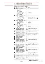
Reassembly
1. Connector Base
• Refer to
table 9-5 “Internal Wiring Harness Parts Checklist (Connec-
fig. 9-5 “Disassembly and Reassembly of the Internal
Wiring Harness (Connector Base)”
.
1. Put the internal wiring harness through the manipulator from the top
part of the S-head.
2. Connect the connector of the connector base box.
3. Connect [LAMP] and [External axis] sticking out from the connector
which are inserted into 4CN of the 1BC connector with the connector
sticking out from the internal wiring harness.
4. Mount the internal wiring harness on the connector base by using the
saddle
and saddle
, and tighten the hexagon socket head cap
screws
with the tightening torque shown in
. It must be
fixed in position with the white mark on the internal wiring harness
facing directly upward.
5. Mount the connector for the internal user I/O wiring harness together
with the gasket
on the connector base unit, and then tighten it with
pan-head sems screws
.
6. Connect the 1BC connector.
7. Mount the ground lead wires (3 wires) by using the cross head APS
bolts .
8. Cover the connectors with tube
, and then tie the openings of the
tube
by using the cable ties
.
9. Connect the grease hose to the back side of the connector base unit.
10. Mount the cross head APS bolts
, and then mount the connector
base on the manipulator.
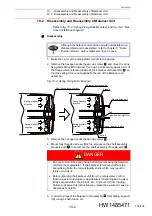
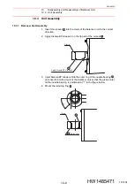
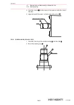
2. S-Head
• Refer to
fig. 9-4 “Disassembly and Reassembly of the Internal Wir-
table 9-4 “Internal Wiring Harness Parts
1. Mount the internal wiring harness on the plate
by using the
hexagon socket head cap screws
, and tighten them with the
tightening torque shown in
. Fix the white-marked part of the
internal wiring harness by using the cable ties
.
2. Connect the “IN” port and the “OUT” port of the multi-port connector of
the S-head to the “IN” connector and the “OUT” connector of the
internal wiring harness respectively.
3. Fix together the “IN” and “OUT” lead wires of the internal wiring
harness and the lead for the encoder of the S- and L-axis by using the
cable tie
.
4. Mount the cover
by using the hexagon socket head cap screws
, and tighten them with the tightening torque shown in
.
5. Insert the power connector to the S- and L-axis motor by aligning the
key position, and then turn the coupling nut on the cable side until it
makes a clicking sound. Confirm that the arrow marks on the
connector on the motor side and the connector on the wiring harness
side match.
6. Fix the internal wiring harness around the S-head with the cable ties
.
9
10
8
5
4
2
7
7
6
1
1
2
6
7
3
4
5
100/134


