2 Adapter Unit Specifications
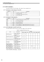
2.5.1 Indicators for the Adapter Tool (PC)
2-6
2.5 LED Indicators
The details and status of the LED display of the Adapter Unit are explained below.
2.5.1 Indicators for the Adapter Tool (PC)
2.5.2 Indicators for the Network
2.5.3 LED Indications when Errors Occur
The LED indications when errors have occurred in the Adapter Unit are shown below.
Note:
{
: Unlit,
z
: Lit,
: Flashing, –: Uncertain
Indication
Color
Explanation
LINK
Yellow
Lit: Ethernet communication in progress
Unlit: Not connected
100M
Green
Lit: 100 Mbps communication in progress
Unlit: Not connected
Indication
Color
Explanation
RDY
Green
Lit when the Adapter unit is operating normally
ERR
Red
Lit: An error has occurred.
Unlit: Operating normally
ST1
Green
Reserved by the system.
ST2
Green
Reserved by the system.
LK1
Green
Lit on establishment of the MECHATROLINK-III CN1 connection
LK2
Green
Lit on establishment of the MECHATROLINK-III CN2 connection
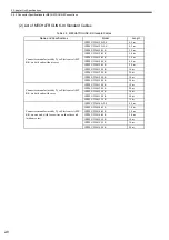
Table 2.3 Indications When Errors Occur
Error
Explanation
Display
RDY
ERR
ST1
ST2
LK1
LK2
LINK 100M
RAM Check Error
RAM error detected
during offline self
diagnosis
{
–
–
–
–
–
–
ROM Checksum Error
ROM error detected
during offline self
diagnosis
{
–
–
–
–
–
–
Adapter Hardware Error
Adapter hardware error
detected during offline
self diagnosis
{
–
–
–
–
–
–
Watchdog
Adapter hardware error
detected during offline
self diagnosis
{
–
–
–
–
–
–
Adapter Tool (PC)
Communication Error
Transmission error
during communication
z
{
–
–
–
–
{
{
MECHATROLINK-
III
Communication Error 1
Transmission error
during communication
z
{
–
–
z
–
–
–
MECHATROLINK-
III
Communication Error 2
Transmission error
during communication
z
{
–
–
–
z
–
–


