


6 Motion Parameters
6.4.3 Motion Monitoring Parameter Details
6-58
( 17 ) Supplemental Information
( 18 ) Absolute Infinite Length Axis Position Control Information
( 19 ) Transparent Command Mode
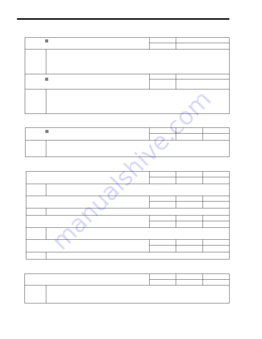
IL
40
Feedback Speed
Setting Range
Setting Unit
−
2
31
to 2
31
−
1
Depends on speed unit.
Description
Stores the feedback speed.
The value is determined by the moving average time constant (fixed parameter 42) and unit set from the difference with
the Machine Coordinate Feedback Position (monitoring parameter IL
16) in each scan.
The setting unit for this parameter depends on the Speed Units (OW
03, bits 0 to 3), but the result of
applying the speed unit setting is not shown here.
IL
42
Torque (Thrust) Reference Monitor
Setting Range
Setting Unit
−
2
31
to 2
31
−
1
Depends on the Torque Unit
(OW
03 bits C to F).
Description
Stores the value of the torque reference.
The Torque (Thrust) Reference Monitor is achieved using the Servo command expansion area and can be executed only
with the MECHATROLINK-II, 32-byte Mode communication method.
The setting unit for this parameter depends on the Torque Unit Selection (OW
03, bits C to F), but
the result of applying the torque unit setting is not shown here.
IL
56
Fixed Parameter Monitor
Setting Range
Setting Unit
−
2
31
to 2
31
−
1
-
Description
Stores the data of the specified fixed parameter number.
This parameter stores the data of the fixed parameter when the Read Fixed Parameter (FIXPRM-RD) is selected in the
Motion Subcommand (setting parameter OW
0A).
IL
5E
Absolute Position at Power OFF (Lower 2 words)
Setting Range
Setting Unit
−
2
31
to 2
31
−
1
pulse
Description
Stores information used for infinite length axis position control when an absolute encoder is used.
The encoder position is normally stored in 4 words.
IL
60
Absolute Position at Power OFF (Upper 2 words)
Setting Range
Setting Unit
−
2
31
to 2
31
−
1
pulse
Description
Same as for IL
5E.
IL
62
Modularized Position at Power OFF (Lower 2 words)
Setting Range
Setting Unit
−
2
31
to 2
31
−
1
pulse
Description
Stores information used for infinite length axis position control when an absolute encoder is used.
These parameters store the axis position managed by the Machine Controller in pulses in 4 words.
IL
64
Modularized Position at Power OFF (Upper 2 words)
Setting Range
Setting Unit
−
2
31
to 2
31
−
1
pulse
Description
Same as for IL
62.
IW
70 to IW
7E
Response Buffer for Transparent Command Mode
Setting Range
Setting Unit
−
−
Description
This area is used for response data when MECHATROLINK Servo commands are specified directly.
・
MECHATROLINK-I and MECHATROLINK-II, 17-byte Mode: Data area = OW
70 to OW
77
・
MECHATROLINK-II, 32-byte Mode: Data area = IW
70 to IW
7E
R
R
R
Summary of Contents for JEPMC-MP2300-Y Series
Page 1: ...MP2300 Machine Controller Basic Module User s Manual Model Number JEPMC MP2300 Y...
Page 10: ...x...
Page 44: ...1 Overview of the MP2300 1 10 MEMO...
Page 62: ...2 System Startup and Sample Programs 2 1 5 Starting and Preparing MPE720 2 18...
Page 358: ...6 Motion Parameters 6 5 7 Acceleration Deceleration Filter Settings 6 68 MEMO...
Page 462: ...7 Motion Commands 7 4 4 Read Fixed Parameters FIXPRM_RD 7 104...
Page 480: ...8 Control Block Diagrams 8 4 2 Control Block Diagram for Speed Control 8 18 MEMO...
Page 524: ...10 Utility Functions 10 14...
Page 574: ...12 Maintenance and Inspection 12 34 MEMO...
Page 596: ...Index Index 6...
Page 598: ......


