background image

Parameter List  A - 2

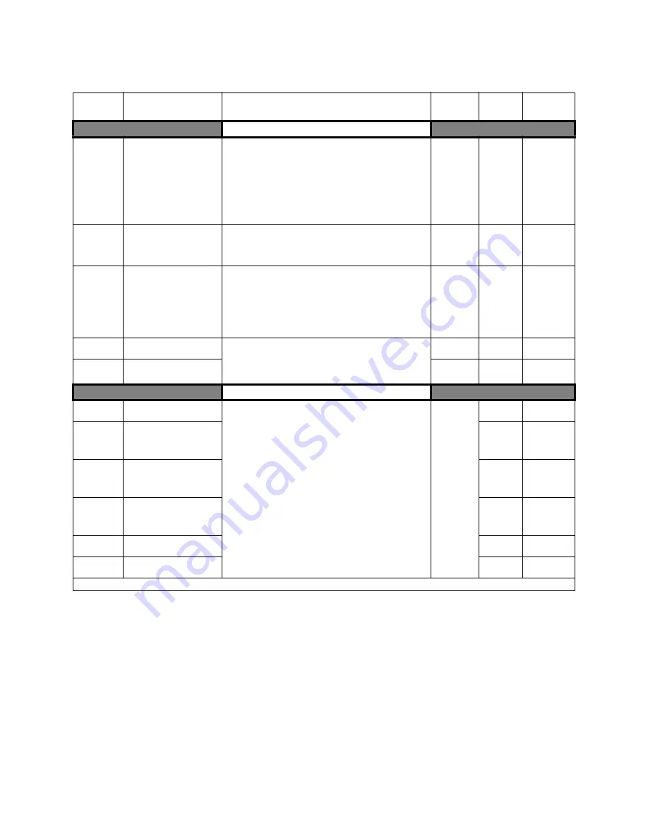
Table 1: E7 Parameter List  

Parameter 

No.

Parameter Name

Digital Operator Display

Description

Setting 

Range

Factory 

Setting

Menu

Location

  Initialization 

A1-00

Language Selection

Select Language

Language selection for digital operator display
0: English   
1: Japanese 
2: Deutsch   
3: Francais 
4: Italiano 
5: Espanol   
6: Portugues
*Not returned to factory setting by initialization

0 to 6

0

Quick Setting

A1-01

Access Level Selection

Access Level

This setting determines which parameters are accessable.
0: Operation Only
1: User Level
2: Advanced Level 

0 to 2

2

Programming

A1-03

Initialize Parameters

Init Parameters

Used to return all parameters to their factory or user setting.
0: No Initialize 
1110: User Initialize (The user must set their own parameter 
default values and then parameter o2-03 must be set to “1” to save 
them. If the parameter values are changed after o2-03 is set to “1”, 
the user default values can be restored by setting A1-03 to 1110.)
2220: 2-Wire Initial
3330: 3-Wire Initial

0 to

3330

0

Programming

A1-04

Password 1 

Enter Password

When the value set into A1-04 does NOT match the value set into 
A1-05, parameters A1-01 thru A1-03 and A2-01 thru A2-32 cannot 
be changed.  All other parameters as determined by A1-01 can be 
changed.  Parameter A1-05 can be accessed by pressing the MENU 
key while holding the RESET key. 

0 to 9999

0

Programming

A1-05

Password 2 

Select Password

0 to 9999

0

Programming

  User Parameters 

A2-01

User Parameter 1

User Param 1

Selects the parameters to be available in the User Access Level 
(A1-01 = 1).  These are the only parameters accessible for the user 
level.  These parameters are not related to the User Initialize    
function.

b1-01

to

o3-02

Programming

A2-02

User Parameter 2

User Param 2

Programming

A2-03

User Parameter 3

User Param 3

Programming

A2-04

User Parameter 4

User Param 4

Programming

A2-05

User Parameter 5

User Param 5

Programming

A2-06

User Parameter 6

User Param 6

Programming

Denotes that parameter can be changed when the drive is running.

Summary of Contents for E7 Drive

Page 1: ...E7 Drive User Manual Model E7U Document Number TM E7 01...

Page 2: ...20 b5 30 0 H3 08 2 n3 01 5 A2 21 b8 01 0 H3 09 2 n3 02 150 A2 22 b8 04 kVA Dep H3 10 100 n3 03 1 A2 23 b8 05 20 H3 11 0 n3 04 40 A2 24 b8 06 0 H3 12 0 3 o1 01 6 A2 25 C1 01 30 H3 13 0 o1 02 1 A2 26 C1...

Page 3: ...n express warranty only as to the quality of its products in conforming to standards and specifications published in the YASKAWA manual NO OTHER WARRANTY EXPRESS OR IMPLIED IS OFFERED YASKAWA assumes...

Page 4: ...he equipment may start unexpectedly upon application of power Clear all personnel from the drive motor and machine area before applying power Secure covers couplings shaft keys and machine loads befor...

Page 5: ...language choices and 5 lines of display with 16 characters per line Optional software allows upload download as well as graphing and monitoring of drive parameters from a PC for ease of drive manageme...

Page 6: ...ion of this product These documents may be provided with the product or upon request Contact Yaskawa Electric America Inc as required Documents may include the following TM E7 02 Programming Manual in...

Page 7: ...n Orientation and Clearances 1 12 Removing and Attaching Terminal Cover 1 13 Removing Attaching Digital Operator and Front Cover 1 14 2 Electrical Installation 2 1 Terminal Block Configuration 2 2 Wir...

Page 8: ...PI Function 5 8 Energy Savings 5 14 Accel Decel Time Settings 5 15 Speed Command Limits 5 15 Input Voltage Setting 5 16 Motor Rated Current Setting 5 16 Option Communication Selection 5 16 Gain And B...

Page 9: ...nance 7 3 Periodic Maintenance of Parts 7 4 Cooling Fan Replacement 7 5 Removing and Mounting the Terminal Card 7 7 If the Motor Rotates Even When Inverter Output is Stopped 7 22 If Zero Volts is Dete...

Page 10: ...Function Code Details D 6 Data Tables D 8 Self Diagnosis D 13 Appendix E Peripheral Devices E 1 Branch Short Circuit Protection E 2 Peripheral Devices E 4 Appendix F Spare Parts F 1 E7 Primary Spare...

Page 11: ...lling the E7 Drive E7 Model Number and Enclosure Style 1 2 Confirmations upon Delivery 1 3 Exterior and Mounting Dimensions 1 7 Checking and Controlling Installation Site 1 11 Installation Orientation...

Page 12: ...R E7U2030 NEMA 1 IP20 CIMR E7U2037 Open Chassis IP00 CIMR E7U2045 Open Chassis IP00 CIMR E7U2075 Open Chassis IP00 CIMR E7U2090 Open Chassis IP00 CIMR E7U2110 Open Chassis IP00 480Vac CIMR E7U40P4 NEM...

Page 13: ...ig 1 1 E7 Drive Nameplate Table 1 2 Received Checks Item Method Has the correct model of Drive been delivered Check the model number on the nameplate on the right side of the Drive Reconcile with pack...

Page 14: ...lectrically charged parts from the front when the Drive is mounted in a control panel also called protected chassis NEMA 1 Type IEC IP20 The Drive is shielded from the exterior and can thus be mounted...

Page 15: ...ive are shown in Fig 1 4 and 1 5 Fig 1 4 Drive Appearance Fig 1 5 Terminal Arrangement Terminal Cover Removed Top protective cover Part of NEMA Type IEC IP20 Front cover Digital Operator Mounting hole...

Page 16: ...6 and 1 7 Fig 1 6 Drive Appearance Fig 1 7 Terminal Arrangement Terminal Cover Removed Mounting holes Cooling fan Nameplate Drive cover Front cover Digital Operator Terminal cover Mounting holes Cool...

Page 17: ...11 02 11 02 11 02 11 02 5 51 5 51 5 51 5 51 28 28 28 28 28 28 28 28 7 87 7 09 7 09 3 07 1 97 1 97 1 4 1 4 10 5 12 4 13 4 13 6 22 5 51 5 51 7 09 6 30 6 30 7 09 1 97 1 97 1 97 1 97 10 10 10 10 3 35 3 35...

Page 18: ...16 6 50 1 4 3 94 5 00 7 88 1 73 5 90 53 11 22 28 15 21 06 10 24 30 12 95 1 36 6 70 1 4 4 13 5 18 1 73 8 07 6 70 88 2 44 2 44 2 44 2 44 1 97 1 97 2 44 2 44 1 97 1 97 1 97 1 97 1 97 1 97 1 97 1 97 1 10...

Page 19: ...264 196 5 12 5 12 5 51 5 12 13 78 14 96 14 17 13 78 2 56 2 56 2 46 2 46 3 8 3 8 3 8 3 8 22 64 23 62 9 84 14 76 49 125 3 94 11 18 2 46 3 8 22 64 23 62 9 84 14 76 49 139 5 12 13 00 2 46 3 8 27 56 28 54...

Page 20: ...02 KJG 7 02 IN ORDER TO ACHIEVE ADEQUATE COOLING THE DRIVE MUST BE POSITIONED TO ALLOW A MINIMUM OF FREE AIR OF 1 2 INCHES ON SIDES AND 5 INCHES TOP AND BOTTOM DIMENSIONS IN INCHES OUTPUT CURRENT RATI...

Page 21: ...on free from harmful gasses and liquids in a location free from excessive vibration in a location free from chlorides in a location away from direct sunlight Controlling the Ambient Temperature To enh...

Page 22: ...n and Clearance IMPORTANT 1 The same clearance is required horizontally and vertically for both Open Chassis IP00 and NEMA 1 Type Drives 2 Always remove the protection covers before installing a CIMR...

Page 23: ...on the left and right at the top of the terminal cover pull down the terminal cover in the direction of arrow 1 and then lift up on the terminal cover in the direction of arrow 2 Fig 1 10 Removing the...

Page 24: ...11 Removing the Digital Operator Removing the Front Cover Press the left and right sides of the front cover in the direction of arrows 1 and lift the bottom of cover in the direction of arrow 2 to rem...

Page 25: ...eled 1 at the top of the control circuit terminal card in the direc tion of arrow 2 Fig 1 13 Removing the Front Cover Attaching the Front Cover Attach the front cover by reversing the procedure to rem...

Page 26: ...row 2 until it snaps in place at B two locations Fig 1 14 Mounting the Digital Operator IMPORTANT 1 Do not remove or attach the Digital Operator or mount or remove the front cover using methods other...

Page 27: ...ribes wiring terminals main circuit terminal connections main circuit terminal wiring specifications control circuit terminals and control circuit wiring specifications Terminal Block Configuration 2...

Page 28: ...8 and smaller Fig 2 2 Terminal Configuration for Models CIMR E7U2022 4030 and larger Fig 2 3 Control Circuit Terminal Layout Charge indicator Ground terminal Control circuit terminals Main circuit ter...

Page 29: ...14 2 23P7 R L1 S L2 T L3 1 2 U T1 V T2 W T3 M4 10 6 to 13 2 1 2 to 1 5 12 to 10 3 5 to 5 5 12 3 5 25P5 R L1 S L2 T L3 1 2 U T1 V T2 W T3 M4 10 6 to 13 2 1 2 to 1 5 10 5 5 10 5 5 27P5 R L1 S L2 T L3 1...

Page 30: ...1 L21 T1 L31 M10 154 8 to 197 9 17 6 to 22 5 3 0 to 4 0 80 to 100 3 0 X 2P 80 X 2P 3 M8 77 4 to 95 0 8 8 to 10 8 10 to 2 0 5 5 to 60 M10 154 8 to 197 9 17 6 to 22 5 3 0 to 400 100 to 200 3 0 100 r l1...

Page 31: ...R L1 S L2 T L3 1 2 U T1 V T2 W T3 M4 10 6 to 13 2 1 2 to 1 5 12 to 10 3 5 to 5 5 12 3 5 14 to 10 2 to 5 5 14 2 47P5 R L1 S L2 T L3 1 2 B1 B2 U T1 V T2 W T3 M4 10 6 to 13 2 1 2 to 1 5 10 5 5 10 5 5 12...

Page 32: ...4 to 39 2 1 to 4 0 50 to 100 1 50 r l1 s200 l2200 s400 l2400 M4 11 4 to 12 3 1 3 to 1 4 20 to 10 0 5 to 5 5 16 1 25 4110 R L1 S L2 T L3 1 M12 276 2 to 344 8 31 4 to 39 2 1 0 to 4 0 50 to 100 1 0 2P 50...

Page 33: ...0 s400 l2400 Use 75 C copper wire or equivalent IMPORTANT Determine the wire size for the main circuit so that line voltage drop is within 2 of the rated voltage Line voltage drop is calculated as fol...

Page 34: ...n Circuit Terminal Functions 208 240Vac and 480Vac Purpose Terminal Designation Model CIMR E7U_ _ _ _ 208 240Vac 480Vac Main circuit power input R L1 S L2 T L3 20P4 to 2110 40P4 to 4300 R1 L11 S1 L21...

Page 35: ...otection for all Drives Failure to use recommended fuses circuit breakers See Appendix E may result in damage to the Drive and or personal injury 2 Control power is supplied internally from the main c...

Page 36: ...on for all Drives Failure to use recommended fuses circuit breakers See Appendix E may result in damage to the Drive and or personal injury 2 Control power is supplied internally from the main circuit...

Page 37: ...resistance of less than 10 3 Do not share the ground wire with other devices such as welding machines motors or large current electrical equipment 4 Always use a ground wire that complies with techni...

Page 38: ...7 Terminal Numbers and Wire Sizes Same for all Drives Terminals Terminal Screws Tightening Torque lb in N m Possible Wire Sizes AWG mm2 Recommended Wire Size AWG mm2 Wire Type S1 S2 S3 S4 S5 S6 S7 SN...

Page 39: ...ion set by H3 09 4 to 20 mA 250 0 to 10 V 20k AC Analog common E G Shield wire optional ground line connection point Digital output signals M1 During Run N O contact CLOSED during operation Multi func...

Page 40: ...itch S1 Location Table 2 9 DIP Switch S1 Name Function Setting S1 1 RS 485 and RS 422 terminating resistance OFF No terminating resistance ON Terminating resistance of 110 S1 2 Input method for analog...

Page 41: ...ng the terminals SN SC and SP An external power supply can also be connected providing more freedom in signal input methods Table 2 10 Sinking Sourcing Mode and Input Signals Internal Power Supply Sin...

Page 42: ...requency Reference 2k MCCB L3 L2 L1 PE 3 Phase Power Supply 50 60Hz External Fault Reverse Run Stop Foward Run Stop Fault Reset Multi step Speed Setting 1 Multi step Speed Setting 2 Jog Frequency Refe...

Page 43: ...ther control circuit terminals 3 If using an optional external power supply ensure it is a UL Listed Class 2 power supply source 4 Use twisted pair or shielded twisted pair cables for control circuits...

Page 44: ...ased on installation needs Fig 2 9 Field Wiring Diagram T L3 S L2 R L1 S3 H1 01 S2 S1 SC E G SP S4 H1 02 S5 H1 03 S6 H1 04 S7 H1 05 SN V 15VDC 20mA A1 0 10VDC 20 K A2 H3 08 4 20mA 250 K 0 to 10VDC 20K...

Page 45: ...line filter can allow High Frequency HF or Low Frequency LF interference to penetrate the power distribution system The basic countermeasures are isolation of the wiring of control and power component...

Page 46: ...2018 2022 FS5973 130 35 130 A 9 48 4 3 3 5315 x 14 40625 x 7 90 x 366 x 180 2030 2037 FS5973 160 40 160 A 13 23 6 4 750 x 17 750 x 6 6875 120 x 451 x 170 2045 FS5973 240 37 240 A 24 25 11 5 125 x 24...

Page 47: ...move any varnish or paint from grounding surfaces Ground the cable shields at both ends Ground the motor of the machine application 4090 FS5972 250 37 250 A 24 25 11 5 125 x 24 x 9 4375 130 x 610 x 24...

Page 48: ...stallation 2 22 Fig 2 11 EMC Filter Layout Metal plate Grounding Remove varnish or paint Grounding Remove varnish or paint Motor cable Length Maximum of Cable length Maximum of 15 75 82 feet M EMC Fil...

Page 49: ...the Digital Operator Digital Operator Display 3 2 Digital Operator Keys 3 3 Drive Mode Indicators 3 4 Drive Main Menus 3 7 Main Menu Structure 3 8 Operation Menu 3 9 Quick Setting Menu 3 12 Programmi...

Page 50: ...Digital Operator are described below Fig 3 1 Digital Operator Component Names and Functions Drive Mode Indicators See Table 3 2 Data Display Displays monitor data parameter numbers and settings Key D...

Page 51: ...will stop If the run command remains closed pressing the AUTO key will restart the Drive While the Drive is running the run command can be opened to stop and closed to restart without taking the Drive...

Page 52: ...requency Reference Selection If the OFF key is pressed the Hand mode speed command will continue to be displayed on the keypad The Drive must to be in a stopped condition before it can be transferred...

Page 53: ...EQ Indicator Indicator Status Hand Mode Auto Mode On The SEQ Indicator will never turn On Parameter b1 02 Run Command Selection is set to terminal strip communications or an option board as indicated...

Page 54: ...Drive is in either the Hand or Auto mode Table 3 5 RUN Indicator Indicator Status Condition On Drive is running Blinking Drive is decelerating to a stop Off Drive is stopped Table 3 6 STOP Indicator I...

Page 55: ...utput current displaying fault his tory or displaying the fault traces Quick Setting QUICK The Drive can be programmed in this menu Use this menu to set read the most commonly used parameters Programm...

Page 56: ...ng the menu selection display press the MENU key repeatedly to scroll between the menu selections Fig 3 2 Main Menu Structure Press the DATA ENTER key to enter the desired menu selection DRIVE Main Me...

Page 57: ...able 3 8 U1 Monitor List Monitor U1 01 Frequency Ref U1 02 Output Freq U1 03 Output Current U1 06 Output Voltage U1 07 DC Bus Voltage U1 08 Output kWatts U1 10 Input Term Sts U1 11 Output Term Sts U1...

Page 58: ...Table 3 9 U2 Fault Trace List Fault Trace Parameters U2 01 Current Fault U2 02 Last Fault U2 03 Frequency Ref U2 04 Output Freq U2 05 Output Current U2 07 Output Voltage U2 08 DC Bus Voltage U2 09 Ou...

Page 59: ...Message 2 U3 03 Fault Message 3 U3 04 Fault Message 4 U3 05 Elapsed Time 1 U3 06 Elapsed Time 2 U3 07 Elapsed Time 3 U3 08 Elapsed Time 4 U3 09 Fault Message 5 U3 10 Fault Message 6 U3 11 Fault Messag...

Page 60: ...t Gain Setting H3 11 Terminal A2 Bias Setting b5 11 PI Output Reverse Selection L2 01 Momentary Power Loss Detection Selection b5 12 PI Feedback Reference Missing Detection Selection L2 02 Momentary P...

Page 61: ...ch b4 Delay Timers b5 PI Control b8 Energy Saving C1 Accel Decel C2 S Curve Acc Dec C4 Torque Comp C6 Carrier Freq d1 Preset Reference d2 Reference Limits d3 Jump Frequencies d4 Sequence E1 V F Patter...

Page 62: ...increase and decrease keys to scroll through the Modified Constants list Auto Tuning Menu This menu is used to auto tune the Drive in order to optimize motor control as well as utilize the bi directio...

Page 63: ...ess the MENU key to scroll to Quick Setting menu 4 Press the MENU key to scroll to Programming menu 5 Press the DATA ENTER key to enter Programming menu 6 Press the INCREASE key until C1 01 Accel Dece...

Page 64: ...er the set data Entry Accepted is dis played for 1 0 sec after the data setting has been confirmed 14 The monitor display for C1 02 returns 15 Press the MENU key to scroll to Operation menu 16 Press t...

Page 65: ...Up 4 1 Chapter 4 Start Up This chapter describes the procedures to prepare the Drive for start up and the procedures to conduct a Drive start up Drive Start Up Preparation 4 2 Drive Start Up Procedure...

Page 66: ...any ______________________________________ Signature ________________________________________ Step 1 The Drive is thoroughly tested at the factory The start up person should verify that the drive is f...

Page 67: ...rive must be solidly grounded using the main circuit ground terminal Ground resistance should be less than 100 for a 208 240Vac Drive Ground resistance should be less than 10 for a 480Vac Drive Select...

Page 68: ...ed If normally closed these contacts may be wired in series with the RUN command contacts which are between terminals S1 and SN of the Drive No special programming is required Refer to Chapter 2 Elect...

Page 69: ...FWD light turns on The RUN light turns on The STOP light is blinking Frequency Ref U1 01 is now displayed on the Digital Operator 7 Press the OFF key 8 Press the MENU key two times Press the DATA ENTE...

Page 70: ...ce to display b1 01 Reference Source This parameter selects where the Drive will receive the speed command Press the DATA ENTER key once Use the or keys and the DATA ENTER key to set this parameter pe...

Page 71: ...tor rotation for the application The RUN light turns on and the STOP light turns off If the direction of motor rotation is wrong press the OFF key The RUN light turns off and the STOP light turns on R...

Page 72: ...mand press the AUTO key so the AUTO SEQ and AUTO REF indicators are on This puts the Drive in Auto mode 20 If using an external speed command determine whether the speed command is a 0 10Vdc or a 4 20...

Page 73: ...until an output of 0 0 Hz is obtained 2 With full scale input adjust Gain H3 02 setting until an output of 60 0 Hz or other desired maximum frequency is obtained For 4 20mA input Terminal A2 1 With 4m...

Page 74: ...Start Up 4 10 Notes...

Page 75: ...5 8 Energy Savings 5 14 Accel Decel Time Settings 5 14 Speed Command Limits 5 15 Input Voltage Setting 5 15 Motor Rated Current Setting 5 16 Option Communication Error Selection 5 16 Gain and Bias Adj...

Page 76: ...rancais French 4 Italiano Italian 5 Espa ol Spanish 6 Portugu s Portuguese Speed Command Source Selection b1 01 Reference Source In order to run the motor in Auto Mode the Drive must receive a run com...

Page 77: ...the Reference Source b1 01 can be taken from the same source e g digital operator terminals or serial communication this is not required To issue a run command from the digital operator Set b1 01 0 a...

Page 78: ...nput Fig 5 3 3 wire Sequence Run Command Example To issue a run command via serial communication Set b1 02 2 Communication and connect RS 485 422 serial communication to R R S and S on the removable t...

Page 79: ...e total time to stop 1 Coast to stop When the run command is removed the Drive will turn off its output transistors The friction of the driven equipment will eventually overcome any residual inertia o...

Page 80: ...se Operation Selection b1 04 Reverse Operation For some applications reverse motor rotation is not applicable and may even cause problems e g fans pumps etc Setting parameter b1 04 to 1 or 3 will caus...

Page 81: ...g The Drive will delay any run command from executing until the b1 11 time has expired During the drive delay time the digital operator will display Both the ALARM and RUN indicators will blink while...

Page 82: ...s b5 01 0 During JOG command is input H3 xx 19 and the termnal status is ON Upper limit Fmax x109 b5 01 3 b5 01 1 Upper limit Fmax x109 Lower limit Fmax x109 Lower limit 0 4 MEMOBUS Reg 06H PI target...

Page 83: ...rtional Gain Setting The proportional gain will apply a straight multiplier to the calculated difference between the PI Setpoint b5 19 and the measured transducer feedback b5 03 Integral Time Setting...

Page 84: ...cting response b5 10 PI Output Gain Setting Applies a multiplier to the output of the PI function Using the gain can be helpful when the PI function is used to trim the Speed Command Increasing b5 10...

Page 85: ...ime determined by the PI Sleep Delay Time b5 16 then the Drive s internal run command drops out and the Drive output ceases Though the Drive s output has ceased all other Drive functions continue Once...

Page 86: ...fore PI was enabled e g the setting of b1 01 b5 19 PI Setpoint Value Parameter b5 19 is a preset PI Setpoint value When b5 18 1 the value of b5 19 will take precedent over any other PI setpoint unless...

Page 87: ...the PI Snooze Delay Time b5 23 the Drive output shuts off This is different from the Sleep Function because it is the feedback that must drop below the PI Snooze Deactivation Level b5 24 before norma...

Page 88: ...square root of the PI output using monitor U1 37 Energy Savings b8 01 Energy Savings Selection When the Energy Savings function is enabled b8 01 1 the Drive reduces the output voltage to the motor bel...

Page 89: ...maximum frequency Input Voltage Setting E1 01 Input Voltage Setting Set the Input Voltage parameter E1 01 to the nominal voltage of the connected AC power supply This parameter adjusts the levels of s...

Page 90: ...arm If F6 01 3 then the fault output is not energized when a communication error occurs All other settings of F6 01 causes the fault output to energize The setting of F6 01 has no effect on the commun...

Page 91: ...unction L2 01 Momentary Power Loss Detection Selection L2 02 Momentary Power Loss Ride thru Time The Drive allows different responses to momentary power losses The setting of L2 01 determines whether...

Page 92: ...Loss Detection Selection L4 06 Frequency Reference at Loss of Frequency Reference The Drive can be configured to compensate for the loss of its external speed command An external speed command is cons...

Page 93: ...thru must be enabled L2 01 1 or 2 Setting H2 01 or H2 02 equal to 1E can configure a digital output as a Restart Enabled to signal if an impending Auto Restart is possible Torque Detection L6 01 Torqu...

Page 94: ...proper detection scheme the Torque Detection Level L6 02 must be specified If the current level read by the output DCCTs rises above overtorque or drops below undertorque and remains there for at leas...

Page 95: ...1 02 and Output Current U1 03 Pressing the INCREASE key once scrolls the monitors to show the User Monitor as selected by o1 01 The factory default for o1 01 is the Output Voltage monitor U1 06 The ac...

Page 96: ...they were set using o2 03 The choice of setting A1 03 1110 is unavailable until the User Initialization has been defined using o2 03 An existing User Initialization can be cleared by setting o2 03 2...

Page 97: ...during deceleration Digital Operator COPY Function o3 01 COPY Function Selection o3 02 Read Allowed Selection The digital operator has parameter COPY capabilities via built in non volatile memory The...

Page 98: ...parameter values into a Drive set o3 01 2 During the writing of the parameter values into the Drive the digital operator will display A successful COPY of the parameter values will display An error m...

Page 99: ...ll not display which parameters did not match only that the verification found discrepancies in some parame ter values Yaskawa Electric America offers DriveWizard software that can also READ COPY and...

Page 100: ...P use the following formula to convert to kW before setting the value of T1 02 kW HP x 0 746 2 In T1 04 enter the Full Load Amps FLA as stamped on the motor s nameplate 3 Press the INCREASE key once t...

Page 101: ...chapter describes diagnostics and troubleshooting for the Drive Fault Detection 6 2 Alarm Detection 6 8 OPE Errors 6 11 Auto Tuning Faults 6 12 Digital Operator Copy Function Faults 6 13 Troubleshooti...

Page 102: ...ERR OP INV Operator Communication Fault 1 Transmission between the Drive and the digital operator cannot be established within 5 seconds after supplying power Digital operator cable not securely conne...

Page 103: ...A D Error Option Card Fault Option card connector connec tion fault Remove all inputs to the option board Option card A D converter fault Perform a factory initialization Cycle power off and on to th...

Page 104: ...Terminal S5 EF6 Ext Fault S6 External Fault at Terminal S6 EF7 Ext Fault S7 External Fault at Terminal S7 Remove the fault from a multi function digital input FBL Feedback Loss PI Feedback Loss This f...

Page 105: ...and the size of the load Recheck the accel decel time C1 01 and C1 02 Recheck the V F pattern E1 01 thru E1 13 Recheck the motor rated current value E2 01 OH4 Motor Overheat 2 Motor Overheating Fault...

Page 106: ...or correction capacitors PF Input Pha Loss Input Phase Loss Drive input power supply has an open phase or has a large imbalance of input voltage Open phase on the input of the Drive Check the input vo...

Page 107: ...circuit and increase the input power to within specifications The acceleration time is set too short Extend the time in C1 01 Voltage fluctuation of the input power is too large Check the input volta...

Page 108: ...ernal sequence logic EF0 Opt External Flt Flashing Communication Option Card External Fault An external fault condition exists Check for an external condition Verify the parameters Verify communicatio...

Page 109: ...nternal Cooling Fan Remove the heating unit OH2 Over Heat 2 Flashing Drive overheat pre alarm signal is input from a multi function digital input terminal An external overheat condition exists connect...

Page 110: ...s set too short Extend the time in C1 01 Voltage fluctuation of the input power is too large Check the input voltage UV2 CTL PS Undervolt Control Power Supply Undervoltage of the control circuit when...

Page 111: ...simultaneously Speed search from maximum frequency and set frequency are set simultaneously Verify program settings H1 01 H1 05 OPE05 Sequence Select Run command is selected through serial communicati...

Page 112: ...auto tuning result became other than the parameter set range Check input data Check motor wiring If a motor and a machine are connected disconnect the motor from the machine Er 09 Accelerate The moto...

Page 113: ...A low Inverter voltage has been detected Repeat the read Replace Digital Operator COPY Function CPE ID UNMATCHED The Drive product code or software number is different Use COPY function for the same p...

Page 114: ...1B is set for a multi function digital input terminal H1 01 to H1 05 If the parameter write enable input is OFF the parameters cannot be changed Turn it ON and then set the parameters Passwords do not...

Page 115: ...the Drive is not in drive mode it will remain in ready status and will not start Press the MENU key once and press the DATA ENTER key The Drive is now in drive mode A 3 wire sequence is in effect The...

Page 116: ...by switching two wires among U TI V T2 and W T3 If the Motor Does Not Put Out Torque or If Acceleration is Slow Use the following information if the motor does not output torque or if acceleration is...

Page 117: ...connected to the Drive output a surge is generated between the Drive switching and the Drive motor coil Normally the maximum surge voltage is three times the Drive s input power supply voltage i e 12...

Page 118: ...g causes are possible There may be resonance between the mechanical system s characteristic frequency and the carrier frequency This is characterized by the motor running with no problems and the mach...

Page 119: ...he DC injection braking is insufficient when starting This can be prevented by slowing motor rotation by DC injection braking before starting the motor Increase parameter b2 03 DC injection braking ti...

Page 120: ...ace the positive red meter lead on terminal R L1 Place the negative black meter lead on terminal 1 Expected reading is about 0 5 Volts 3 Place the positive red meter lead on terminal S L2 Place the ne...

Page 121: ...ero ohms 5 On Drives without a board mounted contactor release the plunger and verify that the resistance is the ohmic value of the soft charge resistor 6 On Drives with a board mounted contactor veri...

Page 122: ...red meter lead on terminal Place the negative black meter lead on terminal U T1 Expected reading is about 0 5 Volts 9 Place the positive red meter lead on terminal Place the negative black meter lead...

Page 123: ...nspection to ensure the fan turns freely 2 If there is no physical evidence that the fan is bad the motor can be checked with a digital mutli meter 3 Set a digital multi meter to the R x 1 scale 4 Mea...

Page 124: ...information is used to determine when a Drive was built to see if it is within its warranty period The date stamp is located on the lower right side of the Drive Fig 6 1 Date Stamp Location PRD INSP2...

Page 125: ...of the Drive Please refer to these instructions to ensure that your Drive receives the proper maintenance to maintain overall performance Periodic Inspection 7 2 Preventive Maintenance 7 3 Periodic Ma...

Page 126: ...pection Corrective Action External terminals mounting bolts connectors etc Are all screws and bolts tight Tighten loose screws and bolts firmly Are connectors tight Reconnect the loose connectors Cool...

Page 127: ...l vibration or noise X AC Power Supply Main circuit control voltage X AC Power Circuit Devices Conductors Wire Connections Loose lugs screws wires Hot spots on parts Corrosion Bent conductors Breakage...

Page 128: ...t Replacement Guidelines Part Standard Replacement Period Replacement Method Cooling fan s 2 to 3 years Replace with new part DC bus capacitors 5 years Replace with new part Determine need by inspecti...

Page 129: ...n the right and left sides of the fan cover in the direction of arrows 1 and then pull the fan out in the direction of arrow 2 3 Pull out the cable connected to the fan from the fan cover and disconne...

Page 130: ...ich the cards are mounted Remove all cables connected to the Control PCB and remove the cooling fan power connector from the fan board 13 PCB positioned near the top of the Drive 4 Remove the cooling...

Page 131: ...to remove the mounting screws completely They are captive and self rising 4 Pull the terminal card out in the direction of the block arrow Mounting the Terminal Card Reverse the removal procedure to...

Page 132: ...Maintenance 7 8 Notes...

Page 133: ...is appendix lists all the parameter numbers and names along with a description of each Also below the parameter name in bold type is the abbreviated name as it appears on the digital operator display...

Page 134: ...default values can be restored by setting A1 03 to 1110 2220 2 Wire Initial 3330 3 Wire Initial 0 to 3330 0 Programming A1 04 Password 1 Enter Password When the value set into A1 04 does NOT match the...

Page 135: ...Parameter 17 User Param 17 Programming A2 18 User Parameter 18 User Param 18 Programming A2 19 User Parameter 19 User Param 19 Programming A2 20 User Parameter 20 User Param 20 Programming A2 21 User...

Page 136: ...mmand accepted in all menus except when b1 02 0 0 or 1 0 Programming b1 11 Drive Delay Time Setting Wait to Run Time After a run command drive output will start after this delay time 0 to 600 0sec Pro...

Page 137: ...ays energized after the digital input is opened 0 0 to 3000 0 0 0sec Programming PI Control b5 01 Proportional Gain Setting PI Mode This parameter enables disables the closed loop PI controller 0 Disa...

Page 138: ...f maximum frequency E1 04 0 to 100 0 Quick Setting b5 23 PI Snooze Delay Time Snooze Delay Time Sets the PI snooze function delay time in terms of seconds 0 to 3600 0sec Quick Setting b5 24 PI Snooze...

Page 139: ...Decel Time 2 Sets the time to decelerate from maximum frequency to zero when selected via a multi function input 30 0sec Programming C1 09 Fast Stop Time Fast Stop Time Sets the time to decelerate fro...

Page 140: ...C6 02 F 0 4 to 15 0 kHz kVA Dependant Programming C6 05 Carrier Frequency Propor tional Gain CarrierFreq Gain Sets the relationship of output frequency to carrier frequency when C6 02 F 0 to 99 0 Pro...

Page 141: ...10 0 0 0 Programming Jump Frequencies d3 01 Jump Frequency 1 Jump Freq 1 These parameters allow programming of up to three prohibited frequency points for eliminating problems with resonant vibration...

Page 142: ...0 to 510 0 480V 240V 480V Programming E1 06 Base Frequency Base Frequency 0 0 to 200 0 60 0Hz Programming E1 07 Mid Output Frequency A Mid Frequency A 0 0 to 200 0 3 0Hz Programming E1 08 Mid Output V...

Page 143: ...BUS fault Active only when a communications option PCB is installed and when b1 01 or b1 02 3 0 Ramp to Stop 1 Coast to Stop 2 Fast Stop 3 Alarm Only 0 to 3 1 Quick Setting F6 02 Input Level of Extern...

Page 144: ...Ext BaseBlk N O Closed Output transistors forced off Open Normal operation 9 Ext BaseBlk N C Closed Normal Operation Open Output transistors forced off A Acc Dec RampHold Closed Acceleration suspende...

Page 145: ...h a multi function digital output 19 PI Disable Turns off the PI controller and PI setpoint becomes speed command 1B Program Lockout Closed All parameter settings can be changed Open Only speed comman...

Page 146: ...1 b1 02 Open Option Card 60 Motor Preheat Applies current to create heat to avoid con densation Closed Apply amount of current as set in parameter b2 09 61 Speed Search 1 When closed as a run command...

Page 147: ...ses when the output current exceeds the value set in parameter L6 02 for more time than is set in parameter L6 03 C Loss of Ref Closes when the drive has detected a loss of analog speed command Speed...

Page 148: ...drive 0 Frequency Bias 0 100 bias 2 Aux Reference B PI Feedback D Frequency Bias 2 0 100 bias E Motor Temperature See parameters L1 03 L1 04 16 PI Differential 1F Not Used 0 to 1F 2 Programming H3 10...

Page 149: ...10V when selected monitor is at 100 output 0 0 to 1000 0 100 0 Programming H4 03 Terminal FM Bias Setting Terminal FM Bias Sets terminal FM output voltage in percent of 10V when selected monitor is a...

Page 150: ...o Stop 2 Fast Stop 3 Alarm Only 0 to 3 3 Programming H5 05 Communication Error Detection Selection Serial Flt Dtct Enables or disables the communications timeout detection function 0 Disabled A commun...

Page 151: ...e trips on UV1 fault when power is lost 1 PwrL Ride Thru t Drive will restart if power returns within the time set in L2 02 2 CPU Power Active Drive will restart if power returns prior to internal pow...

Page 152: ...C bus level drops below the stall prevention level 2 Intelligent The active deceleration rate is ignored and the drive decelerates as fast as possible w o hitting OV fault level 3 Stall prev w R When...

Page 153: ...within the time set in L5 03 restart attempts stop and the fault remains 0 5 to 600 0 10 0sec Quick Setting Torque Detection L6 01 Torque Detection Selection 1 Torq Det 1 Sel Determines the drive s re...

Page 154: ...Sel Controls the Heatsink Cooling Fan Operation 0 Fan On Run Mode Fan will operate only when drive is running and for L8 11 seconds after RUN is removed 1 Fan Always On Cooling fan operates whenever...

Page 155: ...f time the Drive will dwell at E1 09 Minimum Frequency If this time is set too low the machine inertia can cause the motor to rotate slightly after the HSB stop is complete and the Drive output is shu...

Page 156: ...ion A1 03 now allows selecting 1110 for user initialization 2 Clear All Clears the currently saved user initialization A1 03 no longer allows selecting 1110 0 to 2 0 Quick Setting o2 04 Drive kVA Sele...

Page 157: ...isbled the Hand key on the digital operator 0 Disabled 1 Enabled 0 or 1 1 Programming COPY Function o3 01 Copy Function Selection Copy Function Sel This parameter controls the copying of parameters to...

Page 158: ...Sts Displays Drive input terminal status U1 11 Output Terminal Status Output Term Sts Output terminal ON OFF Check U1 12 Drive Operation Status Int Ctl Sts 1 0 1 FWD run Terminal S1 is ON 1 REV run T...

Page 159: ...irst Parameter Causing an OPE OPE Detected Displays the parameter number causing an OPE fault U1 36 PI Input PI Input Displays the error in the PI regulator U1 36 PI Setpoint PI Feedback U1 37 PI Outp...

Page 160: ...tage U2 08 DC Bus Voltage at Most Recent Fault DC Bus Voltage U2 09 Output Power at Most Recent Fault Output kWatts U2 11 Input Terminal Status at Most Recent Fault The format is the same as for U1 10...

Page 161: ...age 5 U3 10 6th Most Recent Fault Fault Message 6 U3 11 7th Most Recent Fault Fault Message 7 U3 12 8th Most Recent Fault Fault Message 8 U3 13 9th Most Recent Fault Fault Message 9 U3 14 10th Most Re...

Page 162: ...Parameter List A 30 Notes...

Page 163: ...Parameters B 1 Appendix B Capacity Related Parameters This appendix lists the parameters affected by the Drive Capacity setting of o2 04 Drive Capacity Selection B 2 Parameters Affected by Drive Capa...

Page 164: ...1 Drive Capacity Selection Voltage E7 Model Number o2 04 Setting 208 240Vac CIMR E7U20P4 0 CIMR E7U20P7 1 CIMR E7U21P5 2 CIMR E7U22P2 3 CIMR E7U23P7 4 CIMR E7U25P5 5 CIMR E7U27P5 6 CIMR E7U2011 7 CIM...

Page 165: ...02 Carrier Frequency Selection CarrierFreq Sel E2 01 Motor Rated Current Motor Rated FLA E2 05 Motor Line to Line Resistance Term Resistance L2 02 Momentary Power Loss Ride thru Time PwrL Ridethru t L...

Page 166: ...Capacity Related Parameters B 4 Notes...

Page 167: ...Specifications C 1 Appendix C Specifications This appendix details the standard Drive Specifications Standard Drive Specifications C 2...

Page 168: ...162 0 192 0 215 0 312 0 Max output voltage V 3 phase 200 208 220 230 or 240Vac Proportional to input voltage Max output frequency Hz 120 Hz Rated voltage V Rated frequency Hz 3 phase 200 208 220 230...

Page 169: ...220 4300 Rated output capacity kVA 46 0 57 0 69 0 85 0 110 0 140 0 160 0 230 0 390 0 Rated output current A 67 2 77 0 96 0 125 0 156 0 180 0 240 0 304 0 506 0 Max output voltage V 3 phase 380 400 415...

Page 170: ...ion Motor protection Protection by electronic thermal overload relay Fuse blown protection Stops for fuse blown Overload protection 110 of rated output current for 60 seconds Overvoltage protection 20...

Page 171: ...tasys communication protocols For details regarding APOGEE FLN please refer to the E7 APOGEE FLN Technical Manual TM E7 21 For details regarding Metasys please refer to the E7 Metasys Technical Manual...

Page 172: ...that the master can perform serial communication using that address Slaves receiving commands from the master perform the specified functions and send a response back to the master Fig D 1 Example of...

Page 173: ...C and the Drive 2 Turn ON the input power to the Drive 3 Set the required communication parameters H5 01 to H5 09 using the Digital Operator 4 Turn OFF the input to the Drive power and check that the...

Page 174: ...or terminals R R S and S 0 No Parity 1 Even Parity 2 Odd Parity 0 to 2 0 Programming H5 04 Stopping Method after Communication Error Serial Fault Sel Selects the stopping method when a communication e...

Page 175: ...s as shown below Data Configure consecutive data by combining the storage register address test code for a loopback address and the data the register contains The data length changes depending on the...

Page 176: ...e slave 2 Drive Fig D 6 Function Code 03H Message Example Write In Single Holding Register 06H Fig D 7 Function Code 06H Message Example Command Message Response Message During Normal Operation Respon...

Page 177: ...age Response Message During Normal Operation Response Message During Error Slave address 01H Slave address 01H Slave address 01H Function code 08H Function code 08H Function code 89H Test Code Higher...

Page 178: ...to F Not used 0002H Frequency reference Set units using parameter o1 03 0003H to 0005H Not used 0006H PI Setpoint 0007H Analog output 1 setting 11 V 726 to 11 V 726 10V 660 0008H Analog output 2 setti...

Page 179: ...at OH1 OH2 Bit 4 Not used Bit 5 Fuse blown PUF Bit 6 PI feedback reference lost FbL Bit 7 External error EF EFO Bit 8 Hardware error CPF Bit 9 Motor overload OL1 or overtorque 1 OL3 detected Bit A PG...

Page 180: ...orque detection 1 Detected Bit C Frequency reference lost 1 Lost Bit D Retrying error 1 Retrying Bit E Error including Modbus communications time out 1 Error occurred Bit F Modbus communications time...

Page 181: ...gnal Bit 0 Run command 1 Operating 0 Stopped Bit 1 Reverse operation command 1 Reverse 0 Forward Bits 2 and 3 Not used Bit 4 External error 1 Fault set using H1 01 Bit 5 Error Fault 1 Reset command se...

Page 182: ...ckets being read or written is outside the range of 1 to 16 In write mode the number of data packets in the message is not No of packets x 2 21H Data setting error Upper limit or lower limit error has...

Page 183: ...erminal S7 Function Selection to 67 Comm Test Mode 2 Turn OFF the power supply to the Drive 3 Perform wiring according to the following diagram while the power supply is turned OFF 4 Turn ON the termi...

Page 184: ...Communications D 14 Notes...

Page 185: ...eripheral Devices E 1 Appendix E Peripheral Devices This appendix describes recommended branch short circuit protection and peripheral devices Branch Short Circuit Protection E 2 Peripheral Devices E...

Page 186: ...6 250 17 Inverse Time 240 7 21P5 9 4 7 8 250 27 Inverse Time 240 15 22P2 13 10 8 250 60 Inverse Time 240 30 23P7 20 16 8 250 200 Inverse Time 240 30 25P5 24 23 250 276 Inverse Time 240 30 27P5 37 31 2...

Page 187: ...7 6 500 59 Inverse Time 480 15 45P5 15 12 5 500 317 Inverse Time 480 30 47P5 20 17 500 317 Inverse Time 480 30 4011 33 27 500 317 Inverse Time 480 50 4015 40 34 500 564 Inverse Time 480 50 4018 48 40...

Page 188: ...nd the operating time 0 1 second or more AC and DC reactor Install a reactor to connect to a power supply transform of large capacity 600 kVA or more or to improve the power factor on the power supply...

Page 189: ...Parts F 1 Appendix F Spare Parts This appendix lists the primary spare parts that may be needed to maintain or service the Drive E7 Primary Spare Parts 208 230 240Vac F 2 E7 Primary Spare Parts 480Va...

Page 190: ...15 D1 D2 2075 N A ETC617093 ETC618021 S3010 ETC618141 SID003116 D1 D6 2090 N A ETC617103 ETC618021 S3010 ETC618141 SID003116 D1 D6 2110 N A ETC617113 ETC618021 S3010 ETC618141 SID003108 D1 D12 Table F...

Page 191: ...5 N A ETC617240 ETC618021 S3010 ETC618141 SID003119 D1 D6 4220 N A ETC617250 ETC618021 S3010 ETC618141 SID003131 D1 D6 4300 N A ETC617260 ETC618021 S3010 ETC618141 SID003119 D1 D12 Table F 4 480Vac E7...

Page 192: ...Spare Parts F 4 Notes...

Page 193: ...26 A 11 Menu 3 7 3 14 Motor Rated Current A 25 Motor Rated Power A 25 B Base Block After Fault 5 18 Circuit Fault 6 2 Minimum Time 5 6 Basic Programming 5 1 to 5 26 Baud Rate 6 8 D 2 D 4 Bias Adjustme...

Page 194: ...ers A 4 Start Frequency 5 5 Time at Start A 4 Time at Stop 5 6 DC Reactor See also Specifications 2 8 E 4 DCInj to Stop 5 6 DDLY Waiting to RUN See Drive Delay Deadband Prohibited Frequency See Jump F...

Page 195: ...Fast Stop Time A 7 Faults Clearing A 25 Covered by Auto Restart 5 19 Digital Output Signal 2 13 Effect on Drive Operation 5 18 History 3 9 to 3 11 A 29 Listing of 6 2 Reset 3 3 Trace 3 9 to 3 11 A 28...

Page 196: ...C IP00 See Open Chassis IEC IP20 See Enclosed wall mounted type IGBT Transistor Module Inspecting 7 2 Resistance Test 6 20 to 6 22 Spare Parts F 2 F 3 INCREASE Key 3 3 Troubleshooting 6 14 Indicators...

Page 197: ...Configuration 5 21 Parameter List 3 9 A 26 A 27 Power On Monitor 5 21 A 22 User Monitor 5 21 5 22 A 23 A 24 MONITOR Key 3 3 MOP Motor Operated Pot Function 5 22 Reference Memory A 9 Motor Auto Tuning...

Page 198: ...alog Outputs H4 01 H4 08 A 17 A 18 Auto Tuning T1 02 T1 04 A 25 Capacity Related B 1 Carrier Freq C6 02 C6 05 A 8 Com OPT Setup F6 01 F6 05 A 11 COPY Function o3 01 o3 02 A 25 DC Braking b2 01 b2 09 A...

Page 199: ...Integral Time Setting 5 9 A 5 Maximum Boost Time 5 13 A 6 Offset Adjustment 5 10 A 5 Output 5 10 Gain Setting 5 10 A 5 Level Selection 5 10 A 5 Limit 5 9 A 5 Square Root Monitor 5 14 A 6 Parameters A...

Page 200: ...it Terminals 2 13 Parameters A 18 Terminating Resistance 2 14 D 3 RTS Control Selection A 18 Run Command During Program A 4 External Troubleshooting 6 15 Selection 3 3 3 5 4 6 5 3 A 4 Source 5 3 RUN I...

Page 201: ...Timer 5 6 DcInj to Stop 5 6 for External Fault from OPT Card A 11 Ramp to Stop 5 5 Stopping Method at Error Modbus Control See Modbus Communications Storage Temperature C 4 Surge Suppressor E 4 Switch...

Page 202: ...5 22 User Parameter Default Value 5 22 A 24 User Parameters A 2 A 3 User Monitor 5 21 5 22 A 23 V Ventilation See Installation Site VERIFY Function 5 25 Error 5 25 6 13 VERIFY Menu See Modified Consta...

Page 203: ...rt associate may refer to this Complete nameplate information from the drive and the motor Confirm that Drive Nameplate Output amps is greater than Motor Nameplate amps list with your parameter settin...

Page 204: ...ingdom Phone 44 12 3673 5000 Fax 44 12 3645 8182 YASKAWA ELECTRIC KOREA CORPORATION Paik Nam Bldg 901 188 3 1 Ga Euljiro Joong Gu Seoul Korea Phone 82 2 776 7844 Fax 82 2 753 2639 YASKAWA ELECTRIC SIN...

Reviews: