


2.2 Block Diagrams
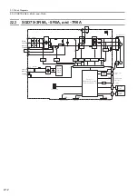
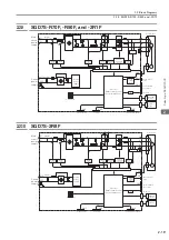
2.2.3 SGD7S-3R8A, -5R5A, and -7R6A
2-12
2.2.3
SGD7S-3R8A, -5R5A, and -7R6A
L1
B1/
B2
B3
L2
L3
1
2
L1C
L2C
U
V
W
CN3
CN2
ENC
CN5
M
CHARGE
-
+
-
-
CN7
CN8
I/O
CN1
Processor
(PWM control, position/
speed calculations, etc.)
Control
power
supply
Digital Operator
Computer
Current
sensor
Dynamic
brake circuit
Servomotor
Gate drive
Analog
voltage
converter
Encoder divided
pulse output
Analog monitor
output
Voltage
sensor
Voltage
sensor
Varistor
Varistor
Relay
drive
Gate drive
overcurrent protection
Temperature
sensor
Safety function signals
Main
circuit
power
supply
Control
power
supply
+
−
+
−
Fan
Status display
I/O signals
INDEXER
Module
Feedback
Module


