background image

SYMBOLS

Keep Bystanders Away

To reduce the risk of injury, user must read and 

understand operator’s manual before using this product.

Keep all bystanders at least 50 ft. away.

Some of the following symbols may be used on this product. Please study them and learn their meaning. Proper inter-

pretation of these symbols will allow you to operate the product better and safer.

Read The Operator’s Manual

Safety Alert

SYMBOL

NAME

DESIGNATION/EXPLANATION

Voltage

Current

Frequency (cycles per second)

Power

Time
Type of current

Type or a characteristic of current
Double-insulated construction

Do not expose to rain or use in damp locations.

Precautions that involve your safety.

Wet Conditions Alert

Class II Construction

Direct Current

Alternating Current

min

Minutes

W

Watt

Hz

Hertz

A

Amperes

V

Volts

Long Hair

Loose Clothing

Failure to keep long hair away from the air inlet could 

result in personal injury.

Failure to keep loose clothing from being drawn into 

air intake could result in personal injury.

Ricochet

Thrown objects can ricochet and result in personal 

injury or property damage.

Sharp Blade

Danger – Keep hands and feet away from blade.

Always wear safety goggles or safety glasses with 

side shields and, as necessary, a full face shield 

when operating this product.

Eye Protection

Failure to keep your hands away from the blade will 

result in serious personal injury.

No Hands Symbol

7

Summary of Contents for 060-3808-8

Page 1: ...Read all safety rules and instructions carefully before operating this tool WARNING Owner s Manual TOLL FREE HELPLINE 1 866 523 5218 WARNING ELECTRIC LAWN EDGER 060 3808 8...

Page 2: ...s 6 Symbols 7 8 Electrical 9 10 Know your edger 11 12 Assembly 12 14 Operation 15 20 Maintenance 21 23 24 Troubleshooting 25 Warranty Parts List 26 27 Specifications Electric lawn edger Replacement bl...

Page 3: ...use product while tired or under the influence of drugs alcohol or medication Do not operate in poor lighting Keep firm footing and balance Do not overreach Overreaching can result in loss of balance...

Page 4: ...ll controls before unplugging Do not use tool if switch does not turn it on or off Any tool that cannot be controlled with the switch is dangerous and must be repaired Do not use with damaged plug If...

Page 5: ...mount ing and any other condition that might effect its operation A guard or other part that is damaged should be properly repaired or replaced by an authorized service center unless indicated elsewh...

Page 6: ...onnect from power supply before attempting to remove any obstruction caught or jammed in the blade installing attachment or making any adjustments To reduce the risk of fire do not allow excessive gra...

Page 7: ...pose to rain or use in damp locations Precautions that involve your safety Wet Conditions Alert Class II Construction Direct Current Alternating Current min Minutes W Watt Hz Hertz A Amperes V Volts L...

Page 8: ...For service we suggest you return the product to your nearest AUTHORIZED SERVICE CENTER for repair When servicing use only identical replacement parts To avoid serious personal injury do not attempt...

Page 9: ...ROVIDED If it will not fit the outlet have the proper outlet installed by a qualified electrician TO AVOID ELECTRICALHAZARDS FIRE HAZARDS OR DAMAGE TO THE TOOL USE PROPER CIRCUITPROTECTION YOUR EDGER...

Page 10: ...damp or wet areas Use a separate electrical circuit for your tools This circuit should not be less than 12 wire and should be protected with a 15 A time delayed fuse Before connecting the motor to the...

Page 11: ...g 2 SWITCH TRIGGER ADJUSTABLE FRONT HANDLE LOCK OFF BUTTON REAR HANDLE CORD RETAINER HANDLE POLE LEVER POWERHEAD POLE EDGER GUARD ADJUSTING KNOB WHEELS BLADE SPRING ASSIST FRONT WHEEL 11 KNOW YOUR EDG...

Page 12: ...igned to fit snugly on top of curbs for improved edging Carefully remove the product and any accesso ries from the box Make sure that all items listed in the packing list are included Inspect the prod...

Page 13: ...e to secure See Figure C 2 Align the slot 5 on the lower power head pole and the opening on the edger Fig A Slide the lower power head pole into the edger until you hear the button click NOTE Handle p...

Page 14: ...ne time assembly is required When removed from the box the front wheel is as shown above A 1 Screw off the adjusting knob from the hole 1 2 Put down the front wheel 3 Insert the adjusting knob into th...

Page 15: ...g product into extension cord NOTE Failure to remove all excess cord slack from extension cord retainer could result in plug loosening from receptacle Do not allow familiarity with this product to mak...

Page 16: ...ueeze the switch trigger The edger will stay ON as long as the trigger switch is squeezed To stop the motor Release the switch trigger Allow at least 5 seconds for blades to stop rotating The edger wi...

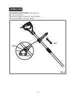
Page 17: ...OPERATION POSITION AUXILIARY HANDLE See Figure 6 Turn the LEVER 90 Adjust the auxiliary handle to the desired position Press the LEVER to the LOCK position UNLOCK LOCK LEVER UP DOWN Fig 6 17...

Page 18: ...to shorten the pole or pull away from each other to lengthen the pole When the desired length is achieved rotate the collar clockwise to secure NOTE Adjust hand placement on the shaft of the edger to...

Page 19: ...stment is complete tighten the adjusting knob securely NOTE Adjust the blade depth from 1 2 in to 1 in deep initially Make a shallow cut to test the cutting depth If the cutting depth needs adjusting...

Page 20: ...dly If the tool slows down back it up an inch or two until the balde comes up to normal speed During edging some sparks may be generated from hitting stones This is normal Do not attempt to edge when...

Page 21: ...se of any other parts may create a hazard or cause product damage MAINTENANCE 21 WARNING Always wear safety goggles or safety glasses with side shields during power tool operation or when blowing dust...

Page 22: ...and inner flange washer Reinstall the inner flange washer onto the edger shaft Center the new blade on the inner flange washer making sure the blade sits flat Install the outer flange washer onto the...

Page 23: ...ored by hanging on a hook by the handle Clean all foreign material from the edger Store it in a place that is inaccessible to children Keep away from corrosive agents such as garden chemicals and de i...

Page 24: ...SOLUTION Motor fails to start when switch trigger is depressed 1 Power cord is not plugged in or connection is loose 2 Household circuit breaker is tripped 1 Plug in the power cord 2 Check circuit bre...

Page 25: ...manship for a period of one hundred twenty 120 days from the date of retail purchase How to Obtain Service Warranty service is available by calling the toll free helpline at 1 866 523 5218 YARDWORDS w...

Page 26: ...26 PARTS LIST...

Page 27: ...3 26 27 28 29 30 31 32 33 34 35 Screw Rear wheel axle Pin Nut M5 6 left rear wheel assy Handle assy Sponge Auxiliary handle assy Connection cap Cord 3 1 1 1 1 1 1 1 2 1 36 37 38 39 40 41 42 3221037 33...

Reviews: