Figure 4
Figure 5
2
1
2
M8
(×3)
1
2
M8×20
(×2)
M8
× 3
4
M8 × 20
× 2
5
16
mm
13
mm
18
mm
19
mm
30
mm
32
mm
16
mm
13
mm
18
mm
19
mm
30
mm
32
mm
×
2
2
1
M8×50
(×2)
Figure 3
16
mm
13
mm
18
mm
19
mm
30
mm
32
mm
×
2
M8 × 50
× 2
3
CHIPPER CONE
DEFLECTOR
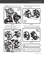
Align the three holes of the chipper intake cone to the three studs
on the rotator disc housing. (See
Figure 4, Illustration 1
) Secure the
intake cone with the M8 nuts from Hardware Kit#4. (See
Figure 4,
Illustration 2
)
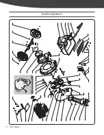
Align the holes in the deflector bracket with the holes in the rotor
disc housing as shown in
Figure 5 illustration 1
. Secure with two
M8×20 bolts from the Hardware Kit#5.
KICKSTAND ROD
Align the top of the kickstand rod holes with the two holes on the
engine mount plate. (See
Figure 3, llustration 1
) Use the two M8×50
bolts, flat washer, and nuts from Hardware Kit#3 to secure the
kickstand. (See
Figure 3, Illustration 2
)
10
2-in-1 Chipper
»
Operator’s Manual
Assembly
|
36060US25M100_KOHLER.indd 10
2017/10/17 11:06:06


