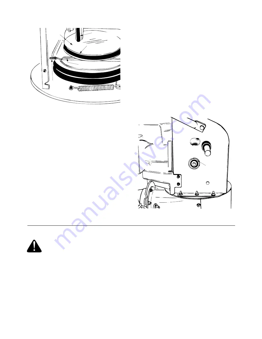
background image

 18

Figure 32  

CHANGING THE FRICTION WHEEL RUBBER

The rubber on the friction wheel is subject to wear
and should be checked after 25 hours of operation,
and periodically thereafter. Replace the friction
wheel rubber if any signs of wear or cracking are
found.

1.

Drain the gasoline from the snow thrower, or
place a piece of plastic under the gas cap.

2.

Tip the snow thrower up and forward, so that it
rests on the auger housing.

3.

Remove six self-tapping screws from the frame
cover underneath the snow thrower.

4.

Remove the klick pins which secure the wheels,
and remove the wheels from the axle.

5.

Using a 7/8" wrench to hold the shaft, loosen,
but do not completely remove, the hex nut and
bell washer on the left end of gear shaft. See
Figure 33.

6.

Lightly tap the hex nut to dislodge the ball
bearing from the right side of frame. Remove
the hex nut and bell washer from left end of
shaft.

7.

Slide the gear shaft to the right and slide the
friction wheel assembly from the shaft. 

8.

Remove the six screws from the friction wheel
assembly (three from each side). Remove the
friction wheel rubber from between the friction
wheel plate.

9.

Reassemble new friction wheel rubber to the
friction wheel assembly, tightening the six
screws in rotation and with equal force.

Position the friction wheel assembly up onto the pin
of the shift rod assembly, and slide the shaft
through the assembly. Reassemble in reverse order.

Figure 33  

SECTION 11:  OFF-SEASON STORAGE

WARNING: 

Never store engine with

fuel in tank indoors or in poorly
ventilated areas, where fuel fumes may
reach an open flame, spark or pilot
light as on a furnace, water heater,
clothes dryer or other gas appliance.

1.

If unit is to be stored over 30 days, prepare the
engine for storage as instructed in the separate
engine operator’s manual included with your
unit. 

2.

Remove all dirt from exterior of engine and
equipment.

3.

Follow lubrication recommendations on page 16.

NOTE:  

When storing any type of power

equipment in a poorly ventilated or metal storage
shed, care should be taken to rust proof the
equipment. Using a light oil or silicone, coat the
equipment, especially any chains, springs, bearings
and cables.

Stop

Bolt

Friction

Wheel 

Disc

Drive Belt

Friction Wheel

Support Bracket

Hex Nut

Bell Washer

Summary of Contents for E602E

Page 1: ...ith a spark arrester meeting applicable local or state laws if any If a spark arrester is used it should be maintained in effective working order by the operator In the State of California the above i...

Page 2: ...ating in reverse 2 PREPARATION Thoroughly inspect the area where the equipment is to be used and remove all door mats sleds boards wires and other foreign objects Disengage all clutches and shift into...

Page 3: ...sengage power to collector impeller when transporting or not in use Use only attachments and accessories approved by the manufacturer of snow thrower such as wheel weights counter weights cabs etc Nev...

Page 4: ...ar frame below the engine The model plate will look like Figure 2 Figure 2 SECTION 3 CALLING CUSTOMER SUPPORT If you are having difficulty assembling this product or if you have any question regarding...

Page 5: ...igned so that the bolts will shear Two replace ment shear bolts and nuts are provided for your convenience Store in a safe place until needed E ATTACHING THE CLUTCH GRIPS Flat Washers 5 16 I D x 5 8 O...

Page 6: ...instructions in this operator s manual to make the job safe and easy You will need the following tools to assemble the snow thrower Attaching the Handle Assembly Hardware A and E Lay loose parts out o...

Page 7: ...d the handle assembly up to the bottom of the snow thrower frame and thread the hex bolt into the lower hole in snow thrower frame Do not tighten at this time See Figure 8 Figure 8 10 Repeat process o...

Page 8: ...he ferrule up or down the shift rod and align with the lower hole on the wider side of the shift lever assembly behind the handle panel See Figure 11 Model 614 644 664 Thread the ferrule onto the shif...

Page 9: ...ssembly facing the front of the unit 2 Place chute flange keepers beneath lip of chute assembly flat side down 3 Insert hex bolt up through chute flange keeper and chute assembly as shown in Figure 14...

Page 10: ...u can depress the auger drive clutch grip against the left handle completely 3 If necessary loosen the hex jam nut and thread the cable in for less slack or out for more slack as necessary Refer to Fi...

Page 11: ...igure 22 for Models 642 and 662 See Figure 23 for Model 614 644 664 The shift lever is located in the center of the handle panel The shift lever may be moved into one of six positions Run engine with...

Page 12: ...on end of the spark plug wire inside the boot is fastened securely over the metal tip on the spark plug See Figure 24 2 Make certain the fuel cutoff valve is in the OPEN vertical position See Figure...

Page 13: ...on page 11 Be certain it snaps into place Do not turn key 3 Rotate choke knob to FULL choke position cold engine start If engine is warm place choke in OFF position instead of FULL 4 Push primer butt...

Page 14: ...y adjustments while engine is running ADJUSTING CHUTE You can control the distance that snow is thrown by adjusting the angle of the chute assembly The sharper the angle the shorter the distance snow...

Page 15: ...up or down the shift rod and align it with the hole closest to the shift knob on the narrow side of the shift lever assembly behind the handle panel NOTE Make certain to check for correct adjustment...

Page 16: ...e old sealant and apply Loctite 5699 or equivalent IMPORTANT Do not overfill the gear case Damage to the seals could result Be sure the vent plug is free of grease in order to relieve pressure SECTION...

Page 17: ...en the bolt and auger pulley See Figure 32 8 Lift the rear auger belt from the auger pulley and slip belt between the support bracket and the auger pulley See Figure 31 Repeat this step for front auge...

Page 18: ...ssembly three from each side Remove the friction wheel rubber from between the friction wheel plate 9 Reassemble new friction wheel rubber to the friction wheel assembly tightening the six screws in r...

Page 19: ...or adjusted by an authorized service dealer Loss of power Spark plug wire loose Gas cap vent hole plugged Exhaust port plugged Connect and tighten spark plug wire Remove ice and snow from cap Be certa...

Page 20: ...20 SECTION 13 ILLUSTRATED PARTS HOUSING ASSEMBLY...

Page 21: ...5 684 0065 Impeller Assembly 1 6 605 5188 Spiral 24 R H 1 605 5192 Spiral 26 R H 1 605 5248 Spiral 30 R H 1 7 605 5189 Spiral 24 L H 1 605 5193 Spiral 26 L H 1 605 5249 Spiral 30 L H 1 8 705 5226 Rei...

Page 22: ...22 HANDLE ASSEMBLY...

Page 23: ...er Pin 5 16 Dia 3 27 732 0193 Comp Spring 38 ID x 88 Lg 1 28 736 0105 Bell Wash 400 ID x 88 OD x 06 1 Model 642 662 Model 614 644 664 29 736 0119 L Wash 5 16 ID 9 31 736 0264 Flat Washer 34 ID x 63 OD...

Page 24: ...24 FRAME ASSEMBLY...

Page 25: ...748 0190 Spacer 1 13 712 0711 Nut Hex 2 38 756 0625 Roller Cable 3 14 714 0126 Key 1 39 784 5590 Frame Shift Bracket 1 15 714 0143 Pin Klick 2 40 784 5638 Cover Frame 1 16 714 0474 Pin Cotter 1 41 784...

Page 26: ...9 Spring 1 13 736 0119 Washer Lock 1 14 736 0242 Washer Bell 1 15 736 0247 Washer Flat 1 Optional Model 614 16 736 0270 Washer Lock 1 17 736 0331 Washer Lock 1 18 736 0505 Washer Flat 1 19 736 0507 Wa...

Page 27: ...4 Belt Cover 1 12 732 0710 Spring 1 13 736 0119 Washer Flat 1 14 736 0242 Washer Bell 1 15 736 0247 Washer Flat 1 16 736 0270 Washer Lock 1 17 736 0331 Washer Bell 1 18 736 0505 Washer Flat 1 19 748 0...

Page 28: ...Department of MTD PRODUCTS INC Transportation charges Transportation charges for the movement of any power equipment unit or attachment are the responsibility of the purchaser Units exported out of th...

Reviews: