background image

21

1

182093

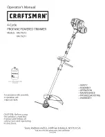
Throttle Housing and Trigger
Assembly (includes 2 & 3)

2

610314

Throttle Trigger Spring

3

180975

Throttle Trigger

4

182068

Throttle Cable Assembly

5

145819

D-Handle Assembly

6

181587

D-Handle Hardware

7

181893

Drive Shaft Housing Assembly

8

153597

Lower Clamp Assembly

9

682064

Flexible Drive Shaft

10

180531

Shield Mounting Screw

11

181784

Bushing Housing Assembly with
Spool Shaft

12

145569

Anti-Rotation Screw

13

683274

Shield and Blade Assembly 
(includes 14)

14

682061

Blade Assembly

15

153619

Outer Spool and Eyelet Assembly
(includes 16)

16

610660

Retainer

17

610317

Spring

18

610318

Inner Reel

19

153066

Bump Head Knob Assembly

*

610375

Replacement Line, 0.80 Diameter 

*

153577

Reel and Line Assembly

*

180897

Bump Head Assembly 
(includes 15-19)

*

682075

Shoulder Strap Assembly

*

182780

Arnold 2-Cycle Oil

*

not shown

MODEL 41AD-280G000

Part No.

Part Description

Ref.

No.

Part No.

Part Description

Ref.

No.

Optional Accessories

Summary of Contents for 41AD-280G000

Page 1: ...ark arrester is used it should be maintained in effective working order by the operator In the State of California the above is required by law Section 4442 of the California Public Resources Code Oth...

Page 2: ...help from our Customer Support Department or an authorized dealer You can locate the model number by looking on the bottom side of the shaft housing next to the shaft grip A sample model plate is exp...

Page 3: ...area of children bystanders and pets At a mini mum keep all children bystanders and pets out side a 50 feet 15 m radius there still may be a risk to bystanders from thrown objects Bystanders should w...

Page 4: ...ories approved by the manufacturer for this unit These are available from your authorized service dealer Use of any non approved parts or accessories could lead to serious injury to the user or damage...

Page 5: ...from operation When turned off they remain hot for a short time SHARP BLADE WARNING Sharp blade on cutting attachment shield To prevent serious injury do not touch line cutting blade DO NOT USE BLADES...

Page 6: ...See Figure 2 5 Tighten the wing nut until the D handle is secure SECTION 2 ASSEMBLING YOUR TRIMMER Installing the Cutting Attachment Shield Use the following instructions if the cutting attach ment s...

Page 7: ...on and off The switch must be in the START position to start the unit See Figure 5 Choke Control The choke control is located above the air filter muffler cover It is used to enrich the fuel mixture w...

Page 8: ...to the unit s fuel tank CAUTION For proper engine operation and maximum reliability pay strict attention to the oil and fuel mixing instructions on the 2 cycle oil container Using improperly mixed fu...

Page 9: ...rmally 2 to 5 pulls NOTE Squeeze the throttle control until the engine has started and warmed up 6 Place the choke lever in the PARTIAL choke position B See Figure 8 NOTE The unit will not run in the...

Page 10: ...Line Length The Bump Head cutting attachment allows you to release trimming line without stopping the engine To release more line lightly tap the cutting attachment on the ground while operating the t...

Page 11: ...0 mm by working from top to bottom in small increments to avoid premature line wear or engine drag Cut from left to right whenever possible Cutting to the right improves the unit s cutting efficiency...

Page 12: ...e idle speed adjuster Refer to MAINTAINING YOUR TRIMMER in Section 6 Adjusting Idle Speed WARNING This unit will need to be running during idle speed adjustment Wear protective clothing and observe al...

Page 13: ...e 15 4 Wash the filter in detergent and water Rinse the filter thoroughly Squeeze out excess water Allow it to dry completely 5 Apply enough clean SAE 30 oil to lightly coat the filter See Figure 16 6...

Page 14: ...12 3 13 5 N m Do not over tighten 0 020 inch 0 5 mm Line Installation This section covers both SplitLine and standard single line installation Always use manufacturer s 0 080 inch 2 03 mm replacement...

Page 15: ...e See Figure 23 Proceed to step 11 SplitLine Installation 8 Take approximately 12 feet 3 65 m of new trim ming line Insert one end of the line through one of the two holes in the inner reel Pull the l...

Page 16: ...ert the ends of the line through the eyelets in the outer spool and place inner reel with spring inside the outer spool See Figure 26 Push the inner reel and outer spool together While holding the inn...

Page 17: ...lled Not enough line is exposed Turn the On Off Stop Control to START Fill fuel tank Press primer bulb fully and slowly 5 7 times Use starting procedure with choke control in the RUN position Drain fu...

Page 18: ...18 SECTION 9 PARTS LIST FOR MODEL 41AD 280G000 42 1 2 3 8 10 12 3 4 5 7 6 11 13 15 16 47 48 43 14 22 49 20 17 18 19 21 26 27 28 31 32 30 33 34 36 37 38 35 25 32 39 40 46 41 44 42 45 24 29 23 9...

Page 19: ...Assembly 27 610303 Square Nut Drive 28 181597 Recoil Pulley Assembly 29 613102 Recoil Spring 30 611061 Rope Guide 31 181889 Pulley Retainer Assembly 32 182827 Switch Assembly includes 39 33 181079 Pul...

Page 20: ...20 MODEL 41AD 280G000 10 8 13 9 17 16 18 19 15 11 12 14 1 1 5 6 7 4 3 2...

Page 21: ...using Assembly with Spool Shaft 12 145569 Anti Rotation Screw 13 683274 Shield and Blade Assembly includes 14 14 682061 Blade Assembly 15 153619 Outer Spool and Eyelet Assembly includes 16 16 610660 R...

Page 22: ...MTD SOUTHWEST INC MTD with respect with new merchandise purchased and used in the United States its possessions and territories MTD warrants this product against defects in material and workmanship fo...

Reviews: