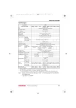

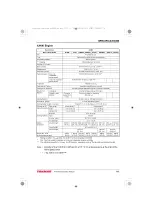
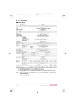

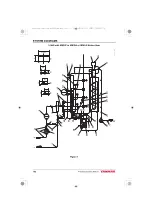

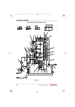


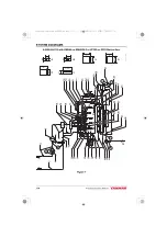
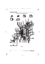


SYSTEM DIAGRAMS
JH Series Operation Manual
169
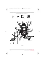
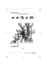
1 – Fuel overflow
2 – * 7 x t4.5 Rubber hose
3 – Fuel inlet
4 – Fuel oil pre-filter
5 – * 7 x t4.5 Rubber hose
6 – Fuel filter (cartridge type)
7 – * 7.5 x t3 Rubber hose
8 – * 9.5 x t3.5 Rubber hose
9 – * 9.5 x t3.5 Rubber hose
10 – * 10 x t1.2 Steel pipe
11 – * 7.5 x t3 Rubber hose
12 – Fuel supply pump
13 – Common rail
14 – Fuel high-pressure pipe 6.35 x
t1.675 Steel pipe
15 – Lubricating oil filter
(cartridge type)
16 – Lubricating oil cooler
17 – Fuel return pipe
18 – 9 x t3.5 Rubber hose
19 – Oil pressure switch
20 – Oil pressure sensor
21 – Fuel injector
22 – 13 x t4 Rubber hose
23 – Marine gear lubrication oil
Cooler
24 – Mixing elbow
25 – 25.4 x t4.3 Rubber hose
26 – 25.4 x t4.3 Rubber hose
27 – Heat exchanger
28 – Main bearing
29 – Lubrication oil inlet strainer
30 – Seawater inlet
31 – 25.4 x t4.3 Rubber hose
32 – Cooling water pump (seawater)
33 – 28 x t4 Rubber hose
34 – 28 x t4 Rubber hose
35 – Hot water connection outlet
36 – Coolant temperature sensor
37 – To Camshaft
38 – Thermostat
39 – From Cylinderhead
40 – To Cylinderblock
41 – Cooling Water Pump (coolant)
42 – Hot water connection return
43 – Lubrication oil pump
44 – Lubrication oil pressure
control valve
45 – 9 x t3.5 Rubber hose
3JH40_4JH45_4JH57_4JH80_4JH110_EN_OPM.book 169 ページ 2022年9月22日 木曜日 午後6時17分


