


A05G069A
3
unused wires must be cut off or covered the metal ends.
⚫
Do not use a inverter as power supply. This cause damage of this product.
⚫
Must drain the pipe before installation. Install pump to a pressured pipe is
extremely high dangerous. It may cause a serious injure of operator.
⚫
Do not operate the pump in a pressure higher than specification , or fluid viscosity
>500 cP or temperature >60
℃
.
⚫
This unit is not suitable for all kind of fluid. Some solvents, extreme acid, high
oxidization high temperature or high viscosity fluid may cause malfunction of pump.
⚫
Wear a chemical protect mask and gloves before repair or maintenance.
⚫
Please do not try to modify the pump or use non-original parts. This damage pump
and cause warranty become invalid.
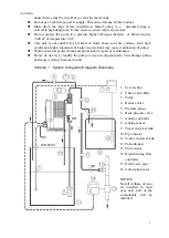
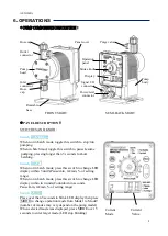
Scheme 1 System configuration diagram (Example)
1.
Level sensor
2.
Check valve/filter
3.
Pump
4.
Release valve
5.
Pressure gauge
6.
Back pressure valve
7.
Analog controller
8.
Analog sensor
9.
Target chemical tank
10.
Pipe injector
11.
Source chemical tank
12.
Pulse damper
13.
Flow sensor
14.
Digital/analog flow
controller
15.
Drain valve pipe
16.
Anit-siphon valve
NOTICE
:
Not all of these devices
are installed. In most
case only part of the
components will be
installed.
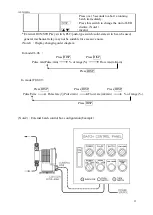
100~240V
AC
OR


