O P E R A T I O N & M A I N T E N A N C E M A N U A L
30
Section 5 Construction of diesel engine
1
、
Cylinder head
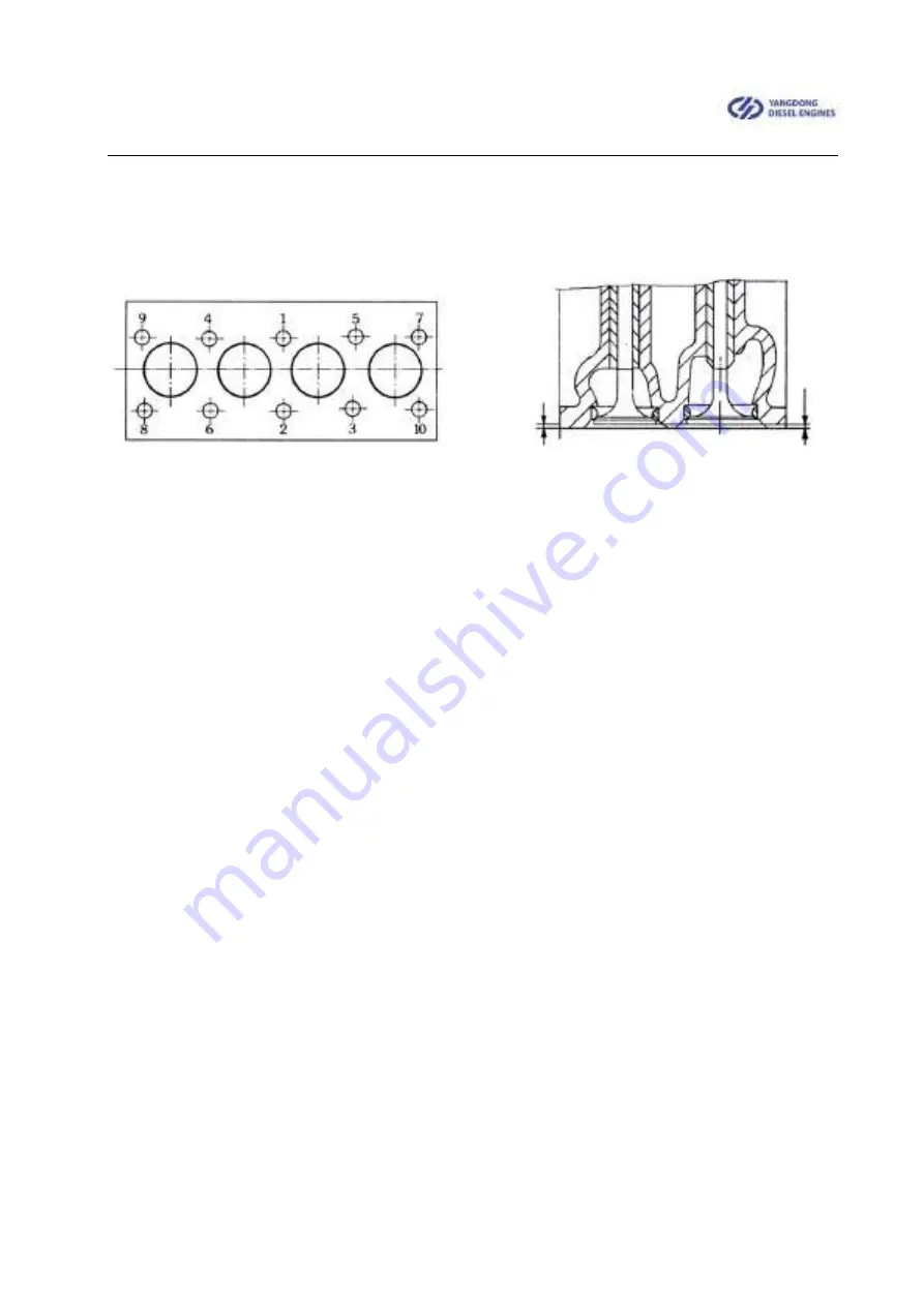
Fig.4 Tightening sequence of cylinder head bolts Fig.5 Valve sinkage
The cylinder head is made of HT200 cast iron (with copper chrome). Fix it on the
cylinder body with bolts for the cylinder head. When tightening the bolts for assembling,
torsion spanner is employed to tighten as the figure 4 indicated below, then the required
tightening force moment is achieved. After the cylinder head has been assembled and
heated for the first time, all the bolts for the cylinder head shall be re-tightened as
required and readjust clearance of the air valves.
The air inlet and air outlet is made of different materials. The air inlet, air outlet and
valve seat have been matched and grinded to avoid air leakage.
When the air valve and seal surface of the valve seat are burned, air leakage,
grinding is required. After grinding is completed, check air leakage of the valve and
inspect the sealing conditions.
The valve seat is made of alloy cast iron. Normal width of the air valve and valve
seat is 1.2-1.6mm. After long-term use and grinding for many times, if the sealing surface
becomes wider which leads to poor sealing, reamer is adopted to amend inner hole
positioning of air valve conduit, then grind the valves and the inner hole positioning as
required.
As for a new one, sinking distance between the plane of the air inlet and air outlet
and the plane of the cylinder head is 0.7-0.9mm, as figure 5 indicated. After amendment
to it for many times, the sinking distance may be increase
d. When it exceeds 2mm, it’s
recommended to change the valve seat.
The valve clearance shall be checked regularly. See Section 1 of chapter V for detail
on adjustment methods. If the valve clearance is excessive, it may affect correctness of


