4-62
TRANSMISSION, SHIFT CAM AND SHIFT FORK
REMOVING THE TRANSMISSION
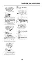
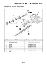
1. Remove:
• Main axle "1"
• Drive axle "2"
• Shift cam
• Shift fork 3
• Shift fork 2
• Shift fork 1
• Remove assembly with the collar
"3" installed to the crankcase.
• Remove assembly carefully. Note
the position of each part. Pay partic-
ular attention to the location and di-
rection of shift forks.
• Remove the main axle, drive axle,
shift cam and shift fork all together
by tapping lightly on the transmis-
sion drive axle with a soft hammer.
CHECKING THE GEARS
1. Inspect:
• Matching dog "a"
• Gear teeth "b"
• Shift fork groove "c"
Wear/damage
→
Replace.
2. Inspect:
• O-ring "1"
Damage
→
Replace.
3. Check:
• Gears movement
Unsmooth movement
→
Repair or
replace.
CHECKING THE BEARING
1. Inspect:
• Bearing "1"
Rotate inner race with a finger.
Rough spot/seizure
→
Replace.
CHECKING THE SHIFT FORK,
SHIFT CAM AND SEGMENT
1. Inspect:
• Shift fork "1"
Wear/damage/scratches
→
Re-
place.
2. Inspect:
• Shift cam "1"
• Segment "2"
Wear/damage
→
Replace.
3. Check:
• Shift fork movement
Unsmooth operation
→
Replace
shift fork.
For a malfunctioning shift fork, re-
place not only the shift fork itself but
the two gears each adjacent to the
shift fork.
INSTALLING THE TRANSMISSION
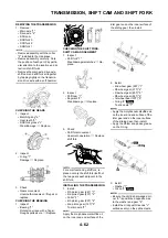
1. Install:
• 5th pinion gear (24T) "1"
• 3rd pinion gear (20T) "2"
• Collar "3"
• 4th pinion gear (22T) "4"
• 2nd pinion gear (16T) "5"
To main axle "6".
Apply the molybdenum disulfide oil
on the inner and end surface of the
idler gear and on the inner surface of
the sliding gear, then install.
2. Install:
• 2nd wheel gear (28T) "1"
• 4th wheel gear (27T) "2"
• 3rd wheel gear (29T) "3"
• 5th wheel gear (25T) "4"
• 1st wheel gear (30T) "5"
• O-ring "6"
To drive axle "7".
• Apply the molybdenum disulfide oil
on the inner and end surface of the
idler gear and on the inner surface
of the sliding gear, then install.
• Apply the lithium soap base grease
on the O-ring.
3. Install:
• Washer "1"
• Circlip "2"
• Be sure the circlip sharp-edged cor-
ner "a" is positioned opposite side
to the washer and gear "b".
• Install the circlip with its ends "c"
settled evenly on the spline crests.
Summary of Contents for YZ250F X 2008
Page 2: ......
Page 3: ...YZ250F X 5XC 28199 34 E0 2008 OWNER S SERVICE MANUAL ...
Page 4: ......
Page 59: ...3 13 ENGINE INTAKE EXHAUST ...
Page 110: ...4 41 OIL PUMP 15 Rotor housing 1 Order Part name Q ty Remarks ...
Page 161: ...5 29 STEERING 9 Bearing race 2 Refer to removal section Order Part name Q ty Remarks ...
Page 170: ...5 38 REAR SHOCK ABSORBER 12 Bearing 2 Refer to removal section Order Part name Q ty Remarks ...
Page 191: ......

