4-58
CRANKCASE AND CRANKSHAFT
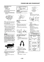
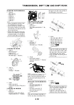
DISASSEMBLING THE
CRANKCASE
1. Separate:
• Right crankcase
• Left crankcase
Separation steps:
a. Remove the crankcase bolts "1",
hose guide "2" and clutch cable
holder "3".
Loosen each bolt 1/4 of a turn at a
time and after all the bolts are loos-
ened, remove them.
b. Remove the right crankcase "4".
• Place the crankcase with its left half
downward and split the right half
apart while lifting it horizontally by
lightly tapping the projection "a" on
it using a soft hammer.
• When splitting it, leave the crank-
shaft and transmission with the left
half.
Use soft hammer to tap on the
case half. Tap only on reinforced
portions of case. Do not tap on
gasket mating surface. Work slow-
ly and carefully. Make sure the
case halves separate evenly. If the
cases do not separate, check for a
remaining case bolt or fitting. Do
not force.
c. Remove the dowel pins and O-
ring.
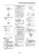
REMOVING THE CRANKSHAFT
1. Remove:
• Crankshaft "1"
Use the crankcase separating
tool "2".
Do not use a hammer to drive out
the crankshaft.
REMOVING THE CRANKCASE
BEARING
1. Remove:
• Bearing "1"
• Remove the bearing from the
crankcase by pressing its inner
race.
• Do not use the removed bearing.
CHECKING THE TIMING CHAIN
AND TIMING CHAIN GUIDE
1. Inspect:
• Timing chain
Cracks/stiff
→
Replace the timing
chain and camshaft sprocket as a
set.
2. Inspect:
• Timing chain guide
Wear/damage
→
Replace.
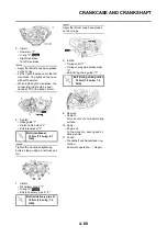
CHECKING THE CRANKCASE
1. Inspect:
• Contacting surface "a"
Scratches
→
Replace.
• Engine mounting boss "b", crank-
case
Cracks/damage
→
Replace.
2. Inspect:
• Bearing
Rotate inner race with a finger.
Rough spot/seizure
→
Replace.
3. Inspect:
• Oil seal
Damage
→
Replace.
CHECKING THE CRANKSHAFT
1. Measure:
• Runout limit "a"
• Small end free play limit "b"
• Connecting rod big end side
clearance "c"
• Crank width "d"
Out of specification
→
Replace.
Use the dial gauge and a thick-
ness gauge.
Crankcase separating
tool:
YU-1135-A/90890-
01135
Dial gauge and stand:
YU-3097/90890-01252
Standard
<Lim-
it>
Runou
t limit:
0.03 mm (0.0012
in)
0.05
mm
(0.002
in)
Small
end
free
play:
0.4–1.0 mm
(0.016–0.039 in)
2.0 mm
(0.08
in)
Side
clear-
ance:
0.15–0.45 mm
(0.0059–0.0177
in)
0.50
mm
(0.02
in)
Crack
width:
55.95–56.00
mm (2.203–
2.205 in)
—
Summary of Contents for YZ250F X 2008
Page 2: ......
Page 3: ...YZ250F X 5XC 28199 34 E0 2008 OWNER S SERVICE MANUAL ...
Page 4: ......
Page 59: ...3 13 ENGINE INTAKE EXHAUST ...
Page 110: ...4 41 OIL PUMP 15 Rotor housing 1 Order Part name Q ty Remarks ...
Page 161: ...5 29 STEERING 9 Bearing race 2 Refer to removal section Order Part name Q ty Remarks ...
Page 170: ...5 38 REAR SHOCK ABSORBER 12 Bearing 2 Refer to removal section Order Part name Q ty Remarks ...
Page 191: ......


