background image

23

CONNECTIONS

PREP

ARA

TION

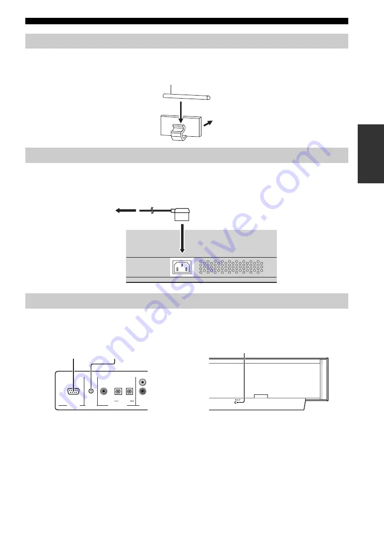
To prevent the optical cable from being unplugged, place the supplied cable clamp with the open side facing upward, 
attach it to the rear panel of this unit in a suitable position and then affix the optical cable in the cable clamp.

Once all other connections are complete, plug one end of the power supply cable into the AC IN terminal of this unit and 
then plug the other end into the AC wall outlet.

The RS-232C, REMOTE IN and IR-OUT terminals do not support normal external component connections. These are 
control expansion terminals for factory use only.

Affixing the optical cable

Connecting the power supply cable

About the RS-232C/REMOTE IN/IR-OUT terminals

Optical cable

Attach to the rear panel of this unit

 To the AC outlet

REMOTE IN

RS-232C

AUDIO

OPTICAL

DIGITAL INPUT

DVD 

AUX

COAXIAL

TV/STB

TV/STB

RS-232C terminal

REMOTE IN terminal

IR-OUT terminal

Summary of Contents for YSP 1000 - Digital Sound Projector Five CH...

Page 1: ...ROIZAT BP70 CROISSY BEAUBOURG 77312 MARNE LA VALLEE CEDEX02 FRANCE YAMAHA ELECTRONICS UK LTD YAMAHA HOUSE 200 RICKMANSWORTH ROAD WATFORD HERTS WD18 7GQ ENGLAND YAMAHA SCANDINAVIA A B J A WETTERGRENS G...

Page 2: ...ades and a third grounding prong The wide blade or the third prong are provided for your safety If the provided plug does not fit into your outlet consult an electrician for replacement of the obsolet...

Page 3: ...ct is found to be the source of interference which can be determined by turning the unit OFF and ON please try to eliminate the problem by using one of the following measures Relocate either this prod...

Page 4: ...tion on common operating errors before concluding that this unit is faulty 16 Before moving this unit press STANDBY ON to set this unit in standby mode and disconnect the AC power plug from the wall o...

Page 5: ...PLAYBACK 39 Selecting the input source 39 Playing back sources 40 Adjusting the volume 40 Muting the sound 41 BEAM MODE 42 5 beam mode 43 Stereo plus 3 beam mode 43 3 beam mode 44 Stereo mode 44 Targ...

Page 6: ...ofers 2 and individual speakers 40 You can fine tune the parameters of this unit to adjust the delay time for separate sound beams resulting in highly directional sound that comes in on the listening...

Page 7: ...igital DTS Digital Theater Systems Dolby Pro Logic Dolby Pro Logic II and DTS Neo 6 Dolby Digital This is the standard audio signal format used on DVDs and other purely digital media This surround tec...

Page 8: ...part as a result of improvements etc In case of differences between the manual and product the product has priority 1 Install this unit in your listening room See INSTALLATION on page 11 2 Connect thi...

Page 9: ...FF CODE SET SPORTS AV POWER STANDBY ON 3 4 5 6 7 8 9 0 10 5BEAM ST 3BEAM 3BEAM TARGET MUSIC MOVIE VOL MODE INPUTMODE MACRO INPUT2 INPUT1 TV STB VCR DVD AUX YSP CINEMA DSP CH TV Remote control 1 Batter...

Page 10: ...ources TV STB VCR DVD or AUX See page 39 for details 5 VOLUME Controls the volume level of all audio channels see page 40 6 STANDBY ON Turns on the power of this unit or sets it to the standby mode se...

Page 11: ...the corresponding decoder of this unit is in operation see page 46 4 Volume level indicator Shows the current volume level see page 40 5 Multi information display Shows information when you adjust the...

Page 12: ...mponent via a composite analog video connection see page 17 0 DVD AUX COMPONENT VIDEO IN jacks Use to connect a DVD player recorder or an external component via a component analog video connection see...

Page 13: ...ts the volume level of each channel see page 84 0 Cursor buttons ENTER Use to select and adjust SET MENU items A TEST Outputs a test tone when adjusting the output level of each speaker see page 83 B...

Page 14: ...D Selects the surround mode for playback see page 46 O MENU Displays the setup menu on your TV monitor see pages 31 62 and 69 The DVD menu is displayed when DVD is selected as the input source P RETUR...

Page 15: ...unit where it will not fall subject to vibrations such as from an earthquake and where it is out of the reach of children When using a cathode ray tube CRT TV do not install this unit directly above y...

Page 16: ...1 Install this unit as close to the exact center of the wall as possible Example 2 Install this unit so that the sound beams can be reflected off the walls Example 3 Install this unit as close to the...

Page 17: ...install the stand or how to mount this unit and the TV on the stand Using a TV stand You can use the optional TV stand to install this unit For detailed information on installing this unit using a TV...

Page 18: ...k etc Do not install this unit on top of a slanted surface This unit may fall over and cause injury Make sure you wipe the surface of the rack etc before securing the fasteners Applying the tape to a...

Page 19: ...dio video input output jacks to connect external components such as your TV DVD player VCR digital satellite tuner cable TV tuner and game console Further by connecting a subwoofer to this unit you ca...

Page 20: ...is made you can enjoy images with better resolution y The circuits of composite and component video signals are independent of each other To prevent the optical cable from being unplugged affix the o...

Page 21: ...pplied cable clamp see page 23 Check that your DVD player recorder is properly set to output Dolby Digital and DTS digital audio signals If not adjust the system settings of your DVD player recorder F...

Page 22: ...match the left and right output jacks of your VCR with the left and right input jacks of this unit Cables used for audio connections Cables used for video connections Connecting a VCR Note REMOTE IN...

Page 23: ...video output jacks connect the component video output jacks of your digital satellite tuner or cable TV tuner to the STB COMPONENT VIDEO IN jacks of this unit Once the component video connection is ma...

Page 24: ...rwave tuner to the STB COMPONENT VIDEO IN jacks of this unit Once the component video connection is made you can enjoy images with better resolution If you want this unit to output audio signals of an...

Page 25: ...o connect a DVD player recorder via an optical digital connection If you connect a DVD player recorder via an optical digital connection adjust settings for INPUT ASSIGNMENT see page 77 Cables used fo...

Page 26: ...your subwoofer and then run AUTO SETUP see page 28 or select SWFR for BASS OUT in SUBWOOFER SET see page 75 Cables used for connections Connecting a subwoofer COMPONENT COMPONENT COMPONENT REMOTE IN...

Page 27: ...the AC IN terminal of this unit and then plug the other end into the AC wall outlet The RS 232C REMOTE IN and IR OUT terminals do not support normal external component connections These are control ex...

Page 28: ...rased in the following cases The remote control is left without batteries for more than 2 minutes Exhausted batteries remain in the remote control The buttons on the remote control are accidentally pr...

Page 29: ...ve different functions depending on the currently selected input source 1 Input selector buttons 2 YSP 3 Beam mode buttons 4 Sound field program buttons 5 Cursor buttons ENTER 6 VOL MODE 7 SURROUND 8...

Page 30: ...display the OSD of this unit on your TV screen It may take a few seconds before this unit s OSD appears on your TV screen If the OSD does not appear use the remote control provided with your TV to swi...

Page 31: ...ls or adjust the settings for the beam mode and the cinema DSP See PLAYBACK on page 39 Run MANUAL SETUP See MANUAL SETUP on page 68 y If you cannot clearly hear a sound beam from a specific speaker ch...

Page 32: ...each beam from this unit and adjusts the delay of each channel so that each sound beam reaches the listening position at the same time EQUALIZING Adjusts frequency and levels of each channel s parame...

Page 33: ...n contact with the walls will be regarded as a protruding part of the walls The best possible results are achieved if the optimizer microphone is placed at the same height as your ears would be when y...

Page 34: ...he cardboard microphone stand originally put together 2 Insert one of the longitudinal shaped part into the crevice of the other longitudinal shaped part 3 Place the circular shaped part on top of the...

Page 35: ...stalled in one of the rooms described in Before installing this unit on page 11 In such cases run BASIC SETUP see page 62 or MANUAL SETUP see page 68 to manually adjust the corresponding parameters If...

Page 36: ...three minutes It is recommended that you should select this optimization feature in the following cases If you make settings for the first time If the unit has been relocated If your listening room ha...

Page 37: ...our listening room Choices SHELF Shelf mount WALL Wall mount Select WALL if the unit is mounted on the wall Select SHELF if the unit is mounted on the shelf REFLECTING Reflecting Use to select the ref...

Page 38: ...lowing screen is displayed temporarily for a few seconds and then disappear from your TV ENVIRONMENT CHECK OK SUB WOOFER CHECK NOT IN USE WILL START in 10 SEC Move aside or behind YSP PREPARATION AUTO...

Page 39: ...on this unit while the AUTO SETUP procedure was in progress Do not perform any other operations while the AUTO SETUP procedure is in progress ERROR E 4 Please check MIC position MIC should be set in...

Page 40: ...control To resume cursor button operations after changing the control area by pressing an input selector button press TEST on the remote control To cancel the SET MENU screen press MENU once more You...

Page 41: ...ntrol buttons used for SET MENU are displayed on the bottom of the screen To return to the previous screen while using SET MENU press RETURN on the remote control To resume cursor button operations af...

Page 42: ...Press ENTER again The new parameters are saved as USER1 USER2 or USER3 Once the parameters are saved the display returns to the SET MENU screen 7 Press MENU to exit The SET MENU screen disappears fro...

Page 43: ...put source and the type of the current input mode are shown in the front panel display Remote control operations Press TV on the remote control to play back a TV program Press STB on the remote contro...

Page 44: ...the output volume is too low increase the volume on this unit to around 25 dB If you have set the appropriate remote control codes for your TV and DVD player you can use the remote control supplied w...

Page 45: ...rily in the front panel display or the numeric value of the current volume level appears if you press VOLUME and the volume level indicator lights up The sound output of all input sources including mu...

Page 46: ...beam and target modes are available in the following cases If you selected Angle to Wall or corner for INSTALLING in AUTO SETUP see page 33 If you selected CORNER RIGHT or CORNER LEFT for INSTALLED P...

Page 47: ...g room The front left and right sound beams are output towards the walls in your listening room Outputs sound beams from the front left and right center and surround left and right speakers This mode...

Page 48: ...t left and right speakers in the 2 channel stereo mode This mode is ideal for playing back hi fi sources such as CDs and can be used to replace your TV speakers Press STEREO on the remote control to s...

Page 49: ...our listening room Press TARGET on the remote control to select the target mode and then press to adjust the angle Control range L90 to R90 Press repeatedly to increase the horizontal angle on the lef...

Page 50: ...e CINEMA DSP programs are turned off see page 55 or when the movie program is selected as the CINEMA DSP program see page 54 Only Dolby Pro Logic Dolby Pro Logic II Movie and DTS Neo 6 Cinema are avai...

Page 51: ...m mode or the 3 beam mode see page 42 1 Press YSP on the remote control to switch to the operation mode of this unit 2 Press SURROUND on the remote control repeatedly or press SURROUND and then press...

Page 52: ...u can no longer hear any audio being output To reduce the TV volume level use the remote control supplied with your TV 4 Press VOLUME on the remote control to adjust the volume level 5 Press SURROUND...

Page 53: ...ss to select PL II Music or Neo 6 Music 3 Press to select the parameter 4 Press to configure the parameter Adjusting surround mode parameters 2 1 STEREO SLEEP CH LEVEL MENU RETURN TEST ENTER SURROUND...

Page 54: ...nd surround channels to the volume balance you desire Control range 3 toward the surround direction to 3 toward the front direction Default setting STD CT WIDTH Distributes the center channel sound to...

Page 55: ...t types of sound reflections that combine with the direct sound coming straight to our ears from the player s instrument to make up the sound field Early reflections Reflected sounds reach our ears ex...

Page 56: ...Jazz Club This program recreates the acoustic environment of The Bottom Line a famous jazz club in New York and lets you feel as if you are seated right in front of the stage Sci Fi Movie This program...

Page 57: ...lets you feel as if you are seated in an actual rock or jazz concert hall 1 Press YSP on the remote control to switch to the operation mode of this unit 2 Press MUSIC on the remote control to select t...

Page 58: ...sound field programs y For detailed descriptions of each sound field program see Sound field program descriptions on page 52 Sports sound field program Select this sound field program when you play s...

Page 59: ...t sound so that each sound field program can reflect your listening environment and your preference even more accurately 1 Press YSP on the remote control to switch to the operation mode of this unit...

Page 60: ...OL MODE on the remote control repeatedly to select NIGHT CINEMA NIGHT MUSIC TV EQUAL VOL or NIGHT OFF Select NIGHT CINEMA when watching films to reduce the dynamic range of film soundtracks and make d...

Page 61: ...d Select Effect Lvl MIN for minimum compression Select Effect Lvl MID for standard compression Select Effect Lvl MAX for maximum compression The volume mode settings are canceled if you press STANDBY...

Page 62: ...current setting TruBass MID TruBass DEEP or TruBass OFF is shown in the front panel display 2 Press on the remote control repeatedly to turn on SRS TruBass TruBass MID or TruBass DEEP is shown in the...

Page 63: ...59 USING TRUBASS BASIC OPERATION 3 Press on the remote control repeatedly to turn off SRS TruBass TruBass OFF is shown in the front panel display VOL TruBass MID TruBass DEEP TruBass OFF...

Page 64: ...tching the amount of time for the sleep timer Each time you press SLEEP on the remote control the front panel display changes as shown below 2 Wait for a few seconds without operating this unit to con...

Page 65: ...isplay indicating that the sleep timer is deactivated The previous setting for the sleep timer before you deactivate it is stored in the system memory and automatically restored when you make a new se...

Page 66: ...s set Displaying the SET MENU screen 1 Press YSP on the remote control to switch to the operation mode of this unit 2 Press MENU on the remote control The SET MENU screen appears on your TV y The cont...

Page 67: ...room is nearest to a rectangle y If the shape of your listening room is irregular select the shape that most closely resembles your room In Example 1 the shape that best describes the listening room i...

Page 68: ...unit in your listening room If RECTANGLE is selected for ROOM TYPE Select WIDE LEFT WIDE CENTER WIDE RIGHT CORNER RIGHT CORNER LEFT NARROW LEFT NARROW CENTER or NARROW RIGHT that best matches the inst...

Page 69: ...reen is not displayed make settings for INSTALLED POSITION 12 Press ENTER Three different room sizes SMALL MID or LARGE are displayed for both SQUARE and RECTANGLE If SQUARE is selected for ROOM TYPE...

Page 70: ...screen is not displayed make settings for ROOM SIZE 15 Press ENTER The following screen appears in the front panel display Select ENTER Enter 3 ROOM SIZE MID 6 2m 4 6m p p ENTER ENTER 4 6 m 15 ft 6 2...

Page 71: ...cel the settings and return to the initial SET MENU screen 17 Press MENU to complete the BASIC SETUP procedure The SET MENU display disappears from your TV screen This completes the parameter settings...

Page 72: ...o manually adjust various parameters related to the sound beam output INPUT MENU Use to manually adjust various parameters related to the audio and video input DISPLAY MENU Use to manually adjust vari...

Page 73: ...ss MENU once more You can also perform the following operations in the front panel display If you press an input selector button during the SET MENU operations the cursor buttons become ineffective In...

Page 74: ...L OR CORNER Corner installation Select FLAT TO WALL if this unit is installed in parallel with the wall in your listening room Adjust the width and length of your listening room as well as the distanc...

Page 75: ...3 5 ft BEAM ADJUSTMENT Beam adjustment Use to manually adjust the various speaker beam angles We recommend that you select 5 beam mode before adjusting these parameters When INSTALLED POSITION is adj...

Page 76: ...l length Use to set the distance that sound beams travel after being output and reflected off the wall until they arrive at the listening position for each speaker The lines in the illustration below...

Page 77: ...t the high frequency output level of each speaker y If the reflection point of the front left and right or surround left and right sound beams is a curtain or other acoustically absorbent surface you...

Page 78: ...ht Adjusts audio signals towards the right The higher the percentage the louder the output from the center Use to manually adjust various parameters related to the sound output SET MENU MANUAL SETUP S...

Page 79: ...setting also determines the routing of LFE low frequency effect signals found in Dolby Digital or DTS sources Choices SWFR subwoofer FRONT Select SWFR if you connect a subwoofer LFE and low frequency...

Page 80: ...ctivity of your listening room Choices NORMAL Normal HI ECHO High echo Select NORMAL if your listening room has a normal reflectivity Select HI ECHO if your listening room has highly reflective surfac...

Page 81: ...cks of this unit Choices TV VCR Select COMPONENT 2 to assign components to the DVD AUX COMPONENT VIDEO IN jacks of this unit Choices DVD AUX Select COMPOSITE 3 to assign components to the DVD AUX VIDE...

Page 82: ...IN jack of this unit Control range 6 0 dB to 0 0 dB Initial setting 3 0 dB INPUT RENAME Input rename Use to change the name of the input source in the OSD and the front panel display Press an input s...

Page 83: ...djust the display position and the background color of the OSD OSD SHIFT OSD shift Use to adjust the vertical position of the OSD Adjust towards the minus direction to raise the position of the OSD an...

Page 84: ...r of this unit MAX VOLUME SET is shown in the front panel display 3 Release INPUT on the front panel 4 Press ENTER on the remote control ADJUSTING SYSTEM PARAMETERS Setting the maximum volume level ST...

Page 85: ...me level will be activated when you turn on the power of this unit next time You can protect the settings currently saved in the system memory from being accidentally erased or unwantedly changed 1 Re...

Page 86: ...all of the parameters of this unit to the factory presets This procedure completely resets ALL the parameters in SET MENU After performing the following procedure you must reset the ROOM TYPE SP POSI...

Page 87: ...appears in the front panel display Using the test tone You can use the test tone feature to output a test tone from each speaker to manually balance the speaker levels Use the test tone to set speaker...

Page 88: ...lso manually adjust the speaker levels while playing back an input source such as a DVD All the speaker levels cannot be adjusted when the stereo mode is selected as the beam mode see page 44 FRONT L...

Page 89: ...PARAMETERS ADVANCED OPERATION 2 Press to adjust speaker volumes Control range 10 dB to 10 dB 3 Press CH LEVEL or wait for a few seconds without operating this unit when you have completed your adjust...

Page 90: ...in most cases DTS Selects only digital signals encoded in DTS Compared to AUTO this input mode provides greater stability while playing back CDs or LDs encoded in DTS ANALOG Selects only analog signa...

Page 91: ...nts on page 88 to operate the external component using the remote control If the external component functions correctly the remote control code setup was successful If the external component does not...

Page 92: ...DVD player operations such as play and stop 4 MENU Displays the DVD menu 5 Cursor buttons Use to select DVD menu items 6 RETURN Use to return to the previous DVD menu screen or exit the DVD menu Contr...

Page 93: ...on buttons for DVD and VCR players Use to perform VCR player operations such as play and stop y Press YSP on the remote control to return to the operation mode of this unit VCR TV POWER 2 1 STEREO SLE...

Page 94: ...E SET on the remote control and then press one of the input selector buttons to select the input source you want to set macros for Proceed to step 2 while holding down CODE SET 2 Press MACRO on the re...

Page 95: ...control to confirm the setting Operating macros 1 Press and hold one of the input selector buttons for approximately 2 seconds to select the input source you want to operate macros for The TV input c...

Page 96: ...les properly If the problem persists the cables may be defective 15 No appropriate input source has been selected Select an appropriate input source with INPUT or the input selector buttons 39 The vol...

Page 97: ...ements was played back Turn down the volume level 40 Select SWFR for BASS OUT 75 Connect a subwoofer and adjust settings for SUBWOOFER SET 75 On screen display does not appear The VIDEO OUT composite...

Page 98: ...s remote control The external component you want to operate is not selected as the input source Press INPUT on the front panel or the input selector buttons on the remote control to select the extern...

Page 99: ...well The Dolby Pro Logic decoder built into this unit employs a digital signal processing system that automatically stabilizes the volume on each channel to enhance moving sound effects and direction...

Page 100: ...ic II 46 DTS 46 DTS Neo 6 46 Dynamic range 76 Fastener 14 Front panel display 7 LFE 0 1 channel 75 95 MANUAL SETUP 68 MEMORY 36 37 Night listening modes 56 On screen display OSD 26 Optical cable 16 19...

Page 101: ...Subwoofer VIDEO 1 Vp p 75 1 Composite COMPONENT VIDEO Y 1 Vp p 75 PB PR 0 5 Vp p 75 1 System Connector Jacks OPTIMIZER MIC 1 Microphone input RS 232C 1 System control REMOTE IN 1 System control IR OU...

Page 102: ...IA 662 SYMPHONIC 662 THOMSON 646 TOSHIBA 634 665 666 667 YAMAHA 699 622 623 647 ZERITH 663 664 VCR ADMIRAL 395 AIWA 396 397 398 329 AKAI 322 323 324 AUDIO DYNAMIC 392 394 BELL HOWELL 393 BLAUPUNKT 325...

Page 103: ...ER ECHOSTAR 822 GE 837 838 839 GENERAL INSTRUMENT 823 HITACHI 824 HUGHES 843 844 845 846 JVC 822 MAGNAVOX 825 PANASONIC 826 829 PHILLIPS 825 843 844 845 846 847 848 849 PRIMESTAR 827 PROSCAN 837 838 8...

Page 104: ...ROIZAT BP70 CROISSY BEAUBOURG 77312 MARNE LA VALLEE CEDEX02 FRANCE YAMAHA ELECTRONICS UK LTD YAMAHA HOUSE 200 RICKMANSWORTH ROAD WATFORD HERTS WD18 7GQ ENGLAND YAMAHA SCANDINAVIA A B J A WETTERGRENS G...

Page 105: ...ophone on an imaginary center line drawn from this unit y Check the following points before starting the AUTO SETUP procedure Is the optimizer microphone firmly connected to this unit Is the optimizer...

Page 106: ...ee page 42 in the supplied Owner s Manual y The target mode outputs sound beams in a single channel and is ideal if you do not want the sound beams to be reflected on the walls in your listening room...

Reviews: