background image

16 – TUTORIAL – Using the notch filters, and the HPF and LPF

YDP2006

5

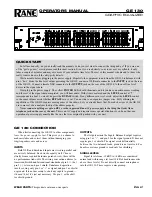
Once you have decided on the frequency for the equal-
izer band, turn the 

G

 rotary encoder to move the

response curve up or down, and the 

Q

 rotary encoder

to adjust the width of the band. The values of F, G and
Q (frequency, gain and resonance) are also given
numerically at the top of the screen. This process can be
repeated for each of the bands, to create the desired set-
tings.

NOTE

Remember that the settings for only one channel are displayed at a time, and you can toggle
between them with the 

[L/<]

 and 

[R/>]

 keys. If you have linked the channels, the channel dis-

played will be the one indicated at the top left of the screen (Lch or Rch).

6

Once the desired settings have been created, don’t for-
get to store them in one of the memory areas, so you can
use them again at a later time.

Using the notch filters, and the HPF and LPF

Besides the HPF and LPF, which are shelving high-pass and low-pass filters, respectively,
the notch filters provide very selective gain cuts, with adjustable Q. One of their main uses
is to filter out sounds that occur at specific frequencies, such as 50/60 Hz AC hum, or the
high frequency noise induced by some fluorescent lighting, or lighting dimmers. Of course,
to avoid affecting the original material any more than necessary, try to use the narrowest
notch possible that will remove the offending signals.
Q is a measure of the resonance of the filter. Basically, the higher the Q, the narrower the
notch. Except for setting the Q, the process for setting the notch filters and the HPF and LPF
is exactly the same (the shelving HPF and LPF don’t have Q).

I. Turning the filters on and off individually

1

You must be in notch mode (the indicator on the

[NOTCH]

 key on). If you are not, then press the 

[NOTCH]

key.

2

Use the 

[L/<]

 or 

[R/>]

 keys to select the appropriate left or

right channel display (in stereo mode), or to choose
between notches MONO.L 1-4, HPF and LPF, and
notches MONO.R 1-4 (in mono mode).

3

Then, ensure the notch or filter is selected for editing
(you may need to press the corresponding selector once
to do this), then press the appropriate selector to toggle
it on/off.

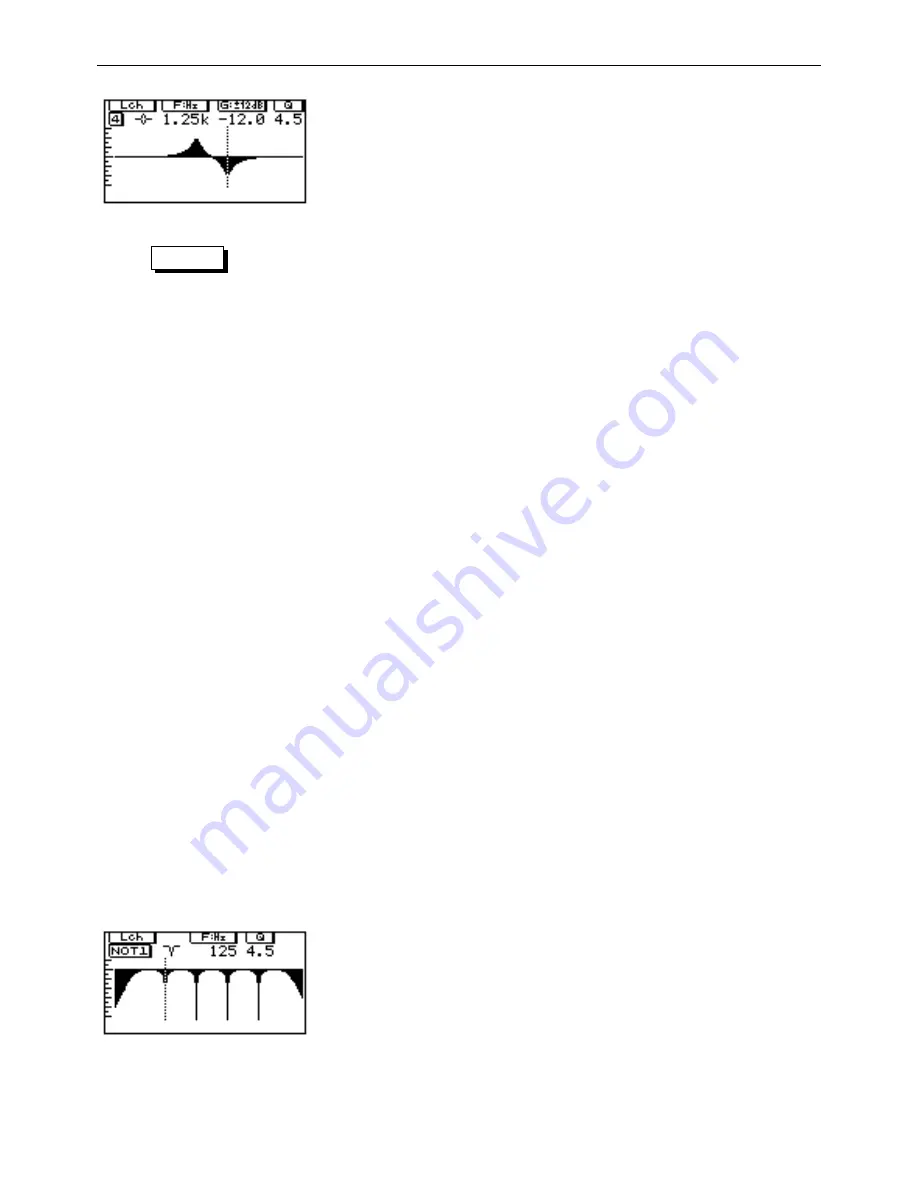
II. Editing the filters graphically

1

Press the 

[NOTCH]

 key until you see a screen similar to

the one here. If you are in mono mode, there are two
screens like this (accessed with the 

[L/<]

 or 

[R/>]

 keys)—

one for notches MONO.L 1-4, HPF and LPF, and one for
notches MONO.R 1-4. The actual settings on your
screen will probably be different to the ones shown
here.

Summary of Contents for YDP2006

Page 1: ...TING MANUAL MANUEL D UTILISATION BEDIENUNGSHANDBUCH INPUT LEVEL 0 10 L R L R CLIP 6 12 18 24 30 36 42 MEMORY PARAMETRIC EQUALIZER F G Q NOTCH 1 2 3 4 HPF LPF STORE RECALL MEMORY PEQ NOTCH UTILITY L R BYPASS POWER ON OFF PEQ 1 2 3 4 5 6 ...

Page 2: ...ce relocate reorient the antenna If the antenna lead in is 300 ohm ribbon lead change the lead in to co axial type cable If these corrective measures do not produce satisfactory results please contact the local retailer authorized to distribute this type of product If you can not locate the appropriate retailer please contact Yamaha Corporation of America Electronic Service Division 6600 Orangetho...

Page 3: ...MP 11 Y 485 NETWORK 11 Y 485 COMM I O 12 PARAMETER COPY 12 SOFTWARE PROTECT 13 MIDI CONTROL 13 DELAY DISPLAY 13 TUTORIAL 14 Finding a suitable memory area in which to store the setting 14 Initializing the memory area 14 Linking the L and R channels 14 Making parametric equalizer settings 15 Using the notch filters and the HPF and LPF 16 I Turning the filters on and off individually 16 II Editing t...

Page 4: ...t a glance exactly which knob or notch filter you are moving Or if you prefer you can change to a purely numeric display for the parametric filter and notch filter param eters One of the biggest advantages of Yamaha digital equalizers apart from their stunning 20 bit sound is the ability to store the equalizer settings you create for instant recall The YDP2006 has the ability to store 40 different...

Page 5: ...tant to prevent damage to the unit itself as well as other connected equipment Handle cables carefully Always plug and unplug cables including the AC cord by gripping the connector not the cord Clean with a soft dry cloth Never use solvents such as benzine or thinner to clean the unit Wipe clean with a soft dry cloth Always use the correct power source Make sure that the power source voltage speci...

Page 6: ...ono mode MONO L 1 4 and HPF and LPF or MONO R 1 4 The indicators show the status of the various bands filters and light when the corre sponding band filter is on 7 MEMORY keys the STORE RECALL and keys are used to read and write settings stored in the 40 memory areas 8 PEQ key pressing this key will show the parameters for the parametric equalizer in either graphic or numerical form and enable the...

Page 7: ...nger than 10 meters If the length of the cable is longer than 100 meters it is recommended that it should be terminated with a resistor matching the impedance of the cable connect a resistor of approx 100 Ω between Pin 2 and Pin 3 2 MIDI IN OUT and THRU These terminals are used for MIDI control of the unit IN is used to receive MIDI data THRU passes along information received at the IN terminal an...

Page 8: ...ting the setting or pressing the RECALL key in the first place and do not want to recall the setting press any key except the RECALL key Remember that the equalization curve shown will be for either the left or the right channel depending on whether the L or R key is lit Storing an equalization setting When you have edited a setting you use the MEMORY and keys to select a memory area where you wan...

Page 9: ... take you through the notch filter and LPF and HPF filter displays NOTE The displays differ in mono and stereo mode To set the mono stereo mode refer to the Utilities section later in the manual Display when in stereo mode PEQ displays Graphical display of all active equalizer bands Numerical display of all equalizer bands Delay and attenuation parameters Notch displays Graphical display of all ac...

Page 10: ...tion bands MONO L 1 6 and MONO R 1 6 If the unit is in notch mode the L and R keys toggle between notches 1 4 HPF LPF MONO L and MONO R notches 1 4 as shown above Display when in mono mode PEQ displays Graphical display of all active equalizer bands MONO L 1 6 on one screen and MONO R 1 6 on the other Numerical display of all equalization bands MONO L 1 6 on one screen and MONO R 1 6 on the other ...

Page 11: ...ate whether or not the corre sponding PEQ band or notch filter is active turned on When the LED on the PEQ key is on the row of indicators refers to the PEQ bands When the LED on the NOTCH key is on the row of indicators refers to the notch and LPF and HPF filters To turn a specific notch filter or PEQ band on or off it must first be selected for editing If the parameters for the desired band are ...

Page 12: ... off Setting it to OFF will work best for most material most of the time Emphasis Use the F encoder to turn emphasis on and off this trips an internal relay so you will hear a click as this is switched Input mode Use the G encoder if you re in mono mode to set the input mode to either L MONO the signal is taken from the left channel input or R MONO the sig nal is taken from the right input This op...

Page 13: ... than the MIDI system Each device on a network belongs to a group and has a device number within that group Use the L and R keys to decide whether you are edit ing the REMOTE or LOCAL settings The LOCAL settings of course refer to this unit and the REMOTE settings refer to a unit to which you will be sending data The F encoder allows you to set up a group number between 1 and 7 The Y 485 protocol ...

Page 14: ...ters plus HPF and LPF and gain for each band of 6dB MONO 12 is a mono 12 band parametric EQ with 8 notch filters plus HPF and LPF and gain for each band of 12dB MONO 6 is a mono 12 band parametric EQ with 8 notch filters plus HPF and LPF and gain for each band of 6dB Select the template you want to use using the F encoder The template will be copied to the edit area After the template settings if ...

Page 15: ...tive bank after you have exited the UTILITY mode Use the F encoder to select the MIDI channel to which the bank will respond OFF 1 through 16 or OMNI Use the G encoder to select the Program Change number which will be recognized Use the Q encoder to select the memory area which will be recalled when the Program Change number set with the G encoder is received NOTE The currently selected Program Ch...

Page 16: ... section Initializing the memory area If you wish to start creating a setting from scratch and there is an existing setting at the memory location you are working at you can clear the existing setting using the PARAME TER COPY function see the Utilities section This will also allow you to set whether the equalizer is in stereo mode 6 PEQ bands and 4 notch filters per channel or mono mode 12 PEQ ba...

Page 17: ...g PEQ selector to select it The number of the band will appear below the channel indication In mono mode press either L or R to toggle between the display of bands MONO L 1 6 and MONO R 1 6 Each band can only be set within a certain frequency range These ranges are shown in the table below As can be seen the ranges overlap to a large degree making them very flexible 3 If you wish to see hear the e...

Page 18: ... hum or the high frequency noise induced by some fluorescent lighting or lighting dimmers Of course to avoid affecting the original material any more than necessary try to use the narrowest notch possible that will remove the offending signals Q is a measure of the resonance of the filter Basically the higher the Q the narrower the notch Except for setting the Q the process for setting the notch f...

Page 19: ...ilar to the one shown The screen shown is the one displayed in stereo mode If you are in mono mode there are two screens like this accessed with the L or R keys one for notches MONO L 1 4 HPF and LPF and one for notches MONO R 1 4 The actual settings on your screen will probably be different to the ones shown here 2 To select a filter for editing if it s not already selected press one of the notch...

Page 20: ...t is often desirable for the sound from various loud speakers to be delayed to compensate for phase delay caused by speaker placement Due to its position in the signal chain the equalization stage is a good place to add this delay The YDP2006 can delay signals by up to 714 milliseconds 242m about 800ft in stereo mode or 1428 milliseconds 485m about 1593ft in mono mode You can input this informa ti...

Page 21: ... impedance 20kΩ Outputs Channel outputs 2 balanced Nominal output level 4 20dBm switchable Maximum output level 24dBm switch at 4dB Output impedance 150Ω A D and D A convertors A D resolution 20 bit linear D A resolution 20 bit linear Frequency response 44 1kHz Memory areas 40 all user programmable MIDI control Program Change messages select memory areas Power requirements USA and Canadian model 1...

Page 22: ...er True Voice X X X Velocity Note ON Note OFF X X X X After Touch Key s Ch s X X X X Pitch Bender X X Control Change X X Prog Change True X O 1 System Exclusive O O Bulk Dump System Common Song Pos Song Sel Tune X X X X X X System Real Time Clock Commands X X X X Aux Messages Local ON OFF All Notes OFF Active Sense Reset X X X X X X X X Notes 1 For program 1 128 memory 1 40 is selected Mode 1 OMNI...

Page 23: ...grams Programmes utilisateur User Programme Unit number ________ Programmer _____________ Backed up to ________ Date ______ Memory area Program name Date Comments 1 2 3 4 5 6 7 8 9 10 11 12 13 14 15 16 17 18 19 20 21 22 23 24 25 26 27 28 29 30 31 32 33 34 35 36 37 38 39 40 ...

Page 24: ...cts Received Selects Received Selects Received Selects 1 33 65 97 2 34 66 98 3 35 67 99 4 36 68 100 5 37 69 101 6 38 70 102 7 39 71 103 8 40 72 104 9 41 73 105 10 42 74 106 11 43 75 107 12 44 76 108 13 45 77 109 14 46 78 110 15 47 79 111 16 48 80 112 17 49 81 113 18 50 82 114 19 51 83 115 20 52 84 116 21 53 85 117 22 54 86 118 23 55 87 119 24 56 88 120 25 57 89 121 26 58 90 122 27 59 91 123 28 60 ...

Page 25: ...s OUTPUT OFF ON 4 20 OFF ON 4 20 A D HA D A ATT L R OFF ON 4 20 OFF ON 4 20 A D HA D A ATT R DSP MIDI IN OUT THRU Y 485 LCD KEY LED F G Q Rotary Encoder ATT HPF LPF 4 band Notch 6 band PEQ Delay 730ms ATT HPF LPF 4 band Notch 6 band PEQ Delay 730ms DSP STEREO MODE ATT HPF LPF 4 band Notch 6 band PEQ Delay 1460ms 4 band Notch 6 band PEQ L R MONO MODE CPU ...

Page 26: ...er Genauigkeit von 1 16 Litiumbatteri Bör endast bytas av servicepersonal Explosionsfara vid felaktig hantering VAROITUS Lithiumparisto Räjähdysvaara Pariston saa vaihtaa ainoastaan aian ammattimies ADVARSEL Lithiumbatteri Eksplosionsfare Udskiftning mà kun foretages af en sagkyndig og som beskrevet i servicemanualen 21 13 16 44 H 45 2 1 3 4 348 13 11 16 W 480 18 7 8 1 2 1 16 3 6 1 8 D 334 9 13 3 ...

Page 27: ...VQ95590 R2 1 CR 72 97 09 500 CR Printed in Japan P O Box 1 Hamamatsu Japan ...

Reviews: