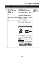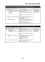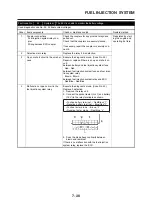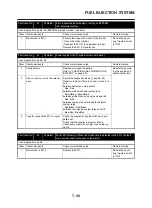
7-25
FUEL INJECTION SYSTEM
EAS00906
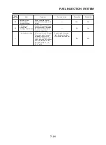
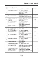
Diagnostic monitoring code table
Fault
Symptom
Probable cause of malfunction
Diagnostic code
code No.
No normal signals are received from
• Open or short circuit in wire harness
the crankshaft position sensor.
• Defective crankshaft position sensor
• Disconnected crankshaft position sensor coupler
_
• Malfunction in A.C. magneto rotor
• Malfunction in ECU
• Improperly installed crankshaft position sensor
Open or short circuit is detected in
• Open or short circuit in wire harness
the intake air pressure sensor.
• Defective intake air pressure sensor
D03
• Disconnected intake air pressure sensor coupler
• Malfunction in ECU
Faulty intake air pressure sensor
• Disconnected, clogged, kinked, or pinched intake air
hose system:
pressure sensor hose
D03
• detected hose
• Defective intake air pressure sensor
• clogged hose.
• Malfunction in ECU
Open or short circuit is detected in
• Open or short circuit in wire harness
the throttle position sensor.
• Defective throttle position sensor
• Disconnected throttle position sensor coupler
D01
• Malfunction in ECU
• Improperly installed throttle position sensor
Stuck throttle position sensor is
• Stuck throttle position sensor
detected.
• Improperly installed throttle position sensor
D01
• Malfunction in ECU
Open circuit in the input line (blue/
• Open circuit in wire harness (ECU coupler)
black lead) of ECU is detected when
• Malfunction in ECU
D20
the start switch is pushed.
Open or short circuit is detected in
• Open or short circuit in wire harness
the coolant temperature sensor.
• Defective coolant temperature sensor
• Disconnected coolant temperature sensor coupler
D06
• Malfunction in ECU
• Improperly installed coolant temperature sensor
Open or short circuit is detected in
• Open or short circuit in wire harness
the intake air temperature sensor.
• Defective intake air temperature sensor
• Disconnected intake air temperature sensor coupler
D05
• Malfunction in ECU
• Improperly installed intake air temperature sensor
No normal signal is received from
• Open or short circuit in wire harness
the O
2
sensor.
• Defective O
2
sensor
_
• Improperly installed sensor
• Malfunction in ECU
The motorcycle has overturned.
• Overturned motorcycle
D08
• Malfunction in ECU
The amount of air-fuel ratio feedback • Open or short circuit in wiring harness
compensation is maintained
• Fuel pressure too low
continuously in the vicinity of the
• Clogged injectors
upper limit (lean air-fuel ratio).
• Defective O
2
sensor (unable to output a rich signal)
_
• Malfunction in other areas of the fuel system
• Malfunction in ECU
The amount of air-fuel ratio feedback • Open or short circuit in wiring harness
compensation is maintained
• Fuel pressure too high
continuously in the vicinity of the
• Faulty injectors (excessive injection volume)
_
lower limit (rich air-fuel ratio).
• Defective O
2
sensor (unable to output a lean signal)
• Malfunction in other areas of the fuel system
• Malfunction in ECU
12
13
14
15
16
19
21
22
24
30
31
32
Summary of Contents for XT660Z 2008
Page 1: ...SERVICE MANUAL 2008 11D F8197 E0 XT660Z ...
Page 8: ......
Page 24: ......
Page 44: ...2 20 TIGHTENING TORQUES Cylinder head tightening sequence 2 4 3 1 ...
Page 54: ...2 30 COOLING SYSTEM DIAGRAMS 1 2 3 4 5 6 7 9 10 11 12 5 8 11 A ...
Page 57: ...2 33 LUBRICATION DIAGRAMS LUBRICATION DIAGRAMS 1 A A A A B B B A A B 3 2 2 4 1 1 5 5 ...
Page 59: ...2 35 LUBRICATION DIAGRAMS A A A A 3 1 2 3 4 ...
Page 60: ...2 36 LUBRICATION DIAGRAMS 1 Oil delivery pipe 2 2 Oil delivery pipe 1 3 Oil filter 4 Oil pump ...
Page 61: ...2 37 LUBRICATION DIAGRAMS 1 7 2 3 4 5 6 A ...
Page 63: ...2 39 LUBRICATION DIAGRAMS 1 6 5 4 3 2 ...
Page 65: ...2 41 CABLE ROUTING CABLE ROUTING ...
Page 67: ...2 43 CABLE ROUTING ...
Page 69: ...2 45 CABLE ROUTING ...
Page 71: ...2 47 CABLE ROUTING ...
Page 73: ...2 49 CABLE ROUTING ...
Page 75: ...2 51 CABLE ROUTING ...
Page 77: ...2 53 CABLE ROUTING ...
Page 79: ...2 55 CABLE ROUTING ...
Page 81: ...2 57 CABLE ROUTING ...
Page 83: ...2 59 CABLE ROUTING ...
Page 176: ...4 56 FRONT FORK WARNING Make sure the brake hoses are routed prop erly 1 2 3 ...
Page 270: ......
Page 284: ......
Page 301: ...7 17 FUEL INJECTION SYSTEM WIRING DIAGRAM ...
Page 324: ......
Page 327: ...8 1 IGNITION SYSTEM EAS27090 IGNITION SYSTEM EAS27110 CIRCUIT DIAGRAM ...
Page 331: ...8 5 ELECTRIC STARTING SYSTEM EAS27160 ELECTRIC STARTING SYSTEM EAS27170 CIRCUIT DIAGRAM ...
Page 337: ...8 11 CHARGING SYSTEM EAS27200 CHARGING SYSTEM EAS27210 CIRCUIT DIAGRAM ...
Page 338: ...8 12 CHARGING SYSTEM 2 A C magneto 5 Rectifier regulator 7 Battery 8 Main fuse ...
Page 340: ...8 14 CHARGING SYSTEM ...
Page 341: ...8 15 LIGHTING SYSTEM EAS27240 LIGHTING SYSTEM EAS27250 CIRCUIT DIAGRAM ...
Page 345: ...8 19 SIGNALING SYSTEM EAS27270 SIGNALING SYSTEM EAS27280 CIRCUIT DIAGRAM ...
Page 351: ...8 25 COOLING SYSTEM EAS00807 COOLING SYSTEM CIRCUIT DIAGRAM ...
Page 354: ...8 28 COOLING SYSTEM ...
Page 355: ...8 29 IMMOBILIZER SYSTEM ET5YU1002 IMMOBILIZER SYSTEM ET5YU1003 CIRCUIT DIAGRAM ...
Page 364: ...8 38 IMMOBILIZER SYSTEM ...
Page 365: ...8 39 ELECTRICAL COMPONENTS EAS27970 ELECTRICAL COMPONENTS ...
Page 367: ...8 41 ELECTRICAL COMPONENTS ...
Page 369: ...8 43 ELECTRICAL COMPONENTS EAS27980 CHECKING THE SWITCHES ...
Page 388: ......
Page 390: ......
Page 396: ...COLOR CODE ...
Page 397: ......
Page 398: ...YAMAHA MOTOR ITALIA S P A ...
Page 399: ...XT660Z 2008 WIRING DIAGRAM ...

