7-28
FUEL INJECTION SYSTEM
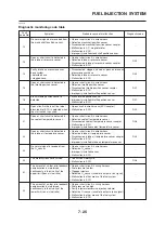
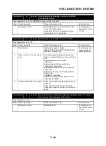
D51
Radiator fan motor relay
The engine stop s
w
itch is set to “
“, the radiator
fan motor relay operates 5 times, 5 seconds each
time (2 seconds on, 3 seconds off), and the engine
tro
ub
le
w
arning light comes on.
• If the engine stop s
w
itch is set to “
”, set it to
“
”, and then set it to “
” again.
Check that the operating so
u
nd of the
radiator fan motor relay is generated
and that the radiator fan motor is
operated 5 times
w
hen the engine
stop s
w
itch is set to “
”.
D52
Headlight relay 1
The engine stop s
w
itch is set to “
”, the headlight
relay operates 5 times, 5 seconds each time (2 sec-
onds on, 3 seconds off), and the engine tro
ub
le
w
arning light comes on.
• If the engine stop s
w
itch is set to “
”, set it to
“
”, and then set it to “
” again.
Check that the operating so
u
nd of the
headlight relay is generated and that
the headlight comes on 5 times
w
hen
the engine stop s
w
itch is set to “
”.
D60
E2PROM fa
u
lt code
display
• Tra nsmits the a
b
normal portion of the data in the
E2PROM that has
b
een detected as fa
u
lt code 44.
01
“00” is displayed
w
hen there is no
malf
u
nction.
D61
Malf
u
nction history code
display
• Displays the codes of the history of the self-diag-
nosis malf
u
nctions (i.e., a code of a malf
u
nction
that occ
u
rred once and
w
hich has
b
een corrected).
• If m
u
ltiple malf
u
nctions ha
v
e
b
een detected, differ-
ent codes are displayed at 2-second inter
v
als, and
this process is repeated.
12 ~ 61
“00” is displayed
w
hen there is no
malf
u
nction.
D62
Malf
u
nction history code
eras
u
re
• Displays the total n
u
m
b
er of codes that are
b
eing
detected thro
u
gh self diagnosis and the fa
u
lt codes
in the past history.
• Erases only the history codes
w
hen the engine
stop s
w
itch is set to “
”. If the engine stop s
w
itch
is set to “
”, set it to “
”, and then set it to “
”
again.
00 ~ 17
“00” is displayed
w
hen there is no
malf
u
nction.
D70
Control n
u
m
b
er
• Displays the program control n
u
m
b
er.
00 ~ 255
Diagnostic
code
Item
Action
Data displayed on the
FI diagnostic tool (reference
v
al
u
e)
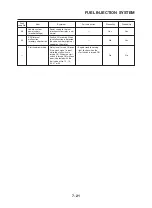
D63
Malf
u
ction code reinstate
(for fa
u
lt code
N
o. 24 only)
•
N
o malf
u
ction code.
“00” is displayed
w
hen there is no
malf
u
nction.
24
• Malf
u
ction code exists.
To reinstate set the engine stop s
w
itch from “ ”
to “ ”.
Summary of Contents for XT660Z 2008
Page 1: ...SERVICE MANUAL 2008 11D F8197 E0 XT660Z ...
Page 8: ......
Page 24: ......
Page 44: ...2 20 TIGHTENING TORQUES Cylinder head tightening sequence 2 4 3 1 ...
Page 54: ...2 30 COOLING SYSTEM DIAGRAMS 1 2 3 4 5 6 7 9 10 11 12 5 8 11 A ...
Page 57: ...2 33 LUBRICATION DIAGRAMS LUBRICATION DIAGRAMS 1 A A A A B B B A A B 3 2 2 4 1 1 5 5 ...
Page 59: ...2 35 LUBRICATION DIAGRAMS A A A A 3 1 2 3 4 ...
Page 60: ...2 36 LUBRICATION DIAGRAMS 1 Oil delivery pipe 2 2 Oil delivery pipe 1 3 Oil filter 4 Oil pump ...
Page 61: ...2 37 LUBRICATION DIAGRAMS 1 7 2 3 4 5 6 A ...
Page 63: ...2 39 LUBRICATION DIAGRAMS 1 6 5 4 3 2 ...
Page 65: ...2 41 CABLE ROUTING CABLE ROUTING ...
Page 67: ...2 43 CABLE ROUTING ...
Page 69: ...2 45 CABLE ROUTING ...
Page 71: ...2 47 CABLE ROUTING ...
Page 73: ...2 49 CABLE ROUTING ...
Page 75: ...2 51 CABLE ROUTING ...
Page 77: ...2 53 CABLE ROUTING ...
Page 79: ...2 55 CABLE ROUTING ...
Page 81: ...2 57 CABLE ROUTING ...
Page 83: ...2 59 CABLE ROUTING ...
Page 176: ...4 56 FRONT FORK WARNING Make sure the brake hoses are routed prop erly 1 2 3 ...
Page 270: ......
Page 284: ......
Page 301: ...7 17 FUEL INJECTION SYSTEM WIRING DIAGRAM ...
Page 324: ......
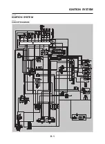
Page 327: ...8 1 IGNITION SYSTEM EAS27090 IGNITION SYSTEM EAS27110 CIRCUIT DIAGRAM ...
Page 331: ...8 5 ELECTRIC STARTING SYSTEM EAS27160 ELECTRIC STARTING SYSTEM EAS27170 CIRCUIT DIAGRAM ...
Page 337: ...8 11 CHARGING SYSTEM EAS27200 CHARGING SYSTEM EAS27210 CIRCUIT DIAGRAM ...
Page 338: ...8 12 CHARGING SYSTEM 2 A C magneto 5 Rectifier regulator 7 Battery 8 Main fuse ...
Page 340: ...8 14 CHARGING SYSTEM ...
Page 341: ...8 15 LIGHTING SYSTEM EAS27240 LIGHTING SYSTEM EAS27250 CIRCUIT DIAGRAM ...
Page 345: ...8 19 SIGNALING SYSTEM EAS27270 SIGNALING SYSTEM EAS27280 CIRCUIT DIAGRAM ...
Page 351: ...8 25 COOLING SYSTEM EAS00807 COOLING SYSTEM CIRCUIT DIAGRAM ...
Page 354: ...8 28 COOLING SYSTEM ...
Page 355: ...8 29 IMMOBILIZER SYSTEM ET5YU1002 IMMOBILIZER SYSTEM ET5YU1003 CIRCUIT DIAGRAM ...
Page 364: ...8 38 IMMOBILIZER SYSTEM ...
Page 365: ...8 39 ELECTRICAL COMPONENTS EAS27970 ELECTRICAL COMPONENTS ...
Page 367: ...8 41 ELECTRICAL COMPONENTS ...
Page 369: ...8 43 ELECTRICAL COMPONENTS EAS27980 CHECKING THE SWITCHES ...
Page 388: ......
Page 390: ......
Page 396: ...COLOR CODE ...
Page 397: ......
Page 398: ...YAMAHA MOTOR ITALIA S P A ...
Page 399: ...XT660Z 2008 WIRING DIAGRAM ...


