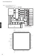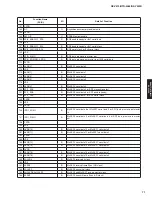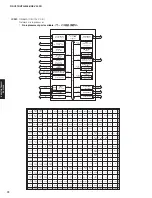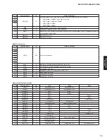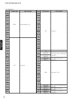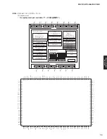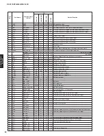
Pin
No.
Port Name
Function Name
(P.C.B.)
I/O
Detail of Function
FULL ON
PPWER OFF
MCU sleep
A
C
OFF
1
VREF
VREF
MCU
MCU
MCU
MCU
AD standard voltage
2
AVCC
AVCC
MCU
MCU
MCU
MCU
Microprocessor power supply
3
SIN4
EEP_MISO
SI
SI
O
SI
EEPROM / Expansion Flash synchronization data input
4
SOUT4
EX_MOSI
SO
SO
O
SO
FL driver / EEPROM / Expansion Flash synchronization data input
5
CLK4
EX_SCK
SO
SO
O
SO
FL driver / EEPROM / Expansion Flash synchronous clock output
6
P9_4
+5EX_PON
O
O
O
O
7
DA0
AMP_LMT
DA
O
O
O
Limiter control output
8
SOUT3
DSP_MOSI
SO
O
O
O
DSP, DIR, DAC synchronization data output
9
SIN3
DSP_MISO
SI
I-
I-
I-
DSP, DIR, DAC synchronization data input
10
CLK3
DSP_SCK
SO
O
O
O
DSP, DIR, DAC synchronous clock output
11
P14_1
HDMI_N_RST
O
O
O
O
HDMI RxTx reset
12
P14_0
TUN_N_RST
O
O
O
O
Tuner reset
13
BYTE
BYTE
MCU
MCU
MCU
MCU
Data bus width reshuffling input / Low: Single chip mode (16bit)
14
CNVSS
E8A_CNVSS
MCU
MCU
MCU
MCU
Processor mode select / Low: Single chip mode
15
P8_7
(no use)
O
O
O
O
(RX-V475/HTR-4066)
DAB_PON
O
O
O
O
(RX-V500D)
16
P8_6
DIAG_FCT
O
O
O
O
Diag OK: Output High / Diag NG: Output Low (default)
17
/RESET
CPU_N_RST
MCU
MCU
MCU
MCU
Reset input
18
XOUT
XOUT
MCU
MCU
MCU
MCU
Oscillation circuit output
19
VSS
DGND
MCU
MCU
MCU
MCU
Microprocessor ground
20
XIN
XIN
MCU
MCU
MCU
MCU
Oscillation circuit input
21
VCC1
+3.3M
MCU
MCU
MCU
MCU
Microprocessor power supply
22
CEC
HDMI_CEC
IO
IO
I+
I+
Microprocessor CEC control
23
N_INT2
DSP_N_INT
IRQ
IRQ
IRQ
O
Interrupt input from DSP
24
N_INT1
HDMI_MUTE
IRQ
I-
I-
I-
HDMI MUTE input / H: Mute
25
N_INT0
HDMI_N_INT
IRQ
I-
I-
I-
Interrupt input from HDMI RxTx
26
TA4IN
DIR_N_INT
TMR
I
O
I
DIR interrupt input
27
P8_0
(no use)
O
O
O
O
28
P7_7
DIR_N_RST
O
O
O
O
DIR reset
29
P7_6
DIR_N_CS
O
O
O
O
DIR chip select
30
TA2IN
TUN_N_INT
TMR
O
O
O
Tuner GPIO2 input
31
P7_4
NCPU_SPI_REQ
I
I
I
I
NET SPI request
32
TA1IN
ACPWR_DET
TMR
I+
I+
I+
AC power detection / L: Power down
33
P7_2
NCPU_SPI_RDY
I
I
I
I
NET SPI ready
34
SCL2
HDMI_SCL
SO
O
O
O
Video decoder, A-video switch I2C SCL output
35
SDA2
HDMI_SDA
SI
O
O
O
Video decoder, A-video switch I2C SDA input and output
36
TXD1
E8A_TXD
SO
SO
I+
I+
37
VCC1
+3.3M
MCU
MCU
MCU
MCU
Microprocessor power supply
38
RXD1
E8A_RXD
SI
SI
I+
I+
39
VSS
DGND
MCU
MCU
MCU
MCU
Microprocessor ground
40
CLK1
E8A_SCLK
SI
SI
I+
I+
41
P6_4
E8A_BUSY
I-
I-
I-
I-
42
SDA0
TUN_SDA
SI
O
O
O
Tuner I2C, Apple co-processor synchronization data input and output
43
SCL0
TUN_SCL
SO
O
O
O
Tuner I2C, Apple co-processor synchronous clock output
44
P6_1
(no use)
O
O
O
O
45
P6_0
(no use)
O
O
O
O
46
P13_7
VOL_MOSI
O
O
O
O
Electronic volume flip-flop synchronization data output
47
P13_6
VOL_SCK
O
O
O
O
Electronic volume flip-flop synchronous clock output
48
P13_5
I_PRT
I-
I-
I-
I-
Overcurrent protection detection
49
P13_4
TRANS_RY
O
O
O
O
50
P5_7
DCDC_PON
O
O
O
O
51
P5_6
MT_N_SW
O
O
O
O
Mute control (Subwoofer)
52
P5_5
E8A_N_EPM
I-
I-
I-
I-
80
RX-V475/HTR-4066/RX-V500D
RX-V475/HTR-4066/
RX-V50
0D
Summary of Contents for RX-V500D
Page 9: ...RX V500D A model RX V500D B G models 9 RX V475 HTR 4066 RX V500D RX V475 HTR 4066 RX V500D ...
Page 132: ... CONFIGURING THE SYSTEM SETTINGS RX V475 HTR 4066 RX V500D 133 ...
Page 133: ... システム設定を変更する RX V475 HTR 4066 RX V500D 134 ...
Page 146: ...147 RX V475 HTR 4066 RX V500D RX V475 HTR 4066 RX V500D MEMO ...
Page 147: ...RX V475 HTR 4066 RX V500D ...


