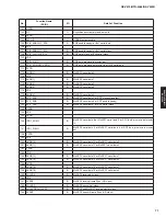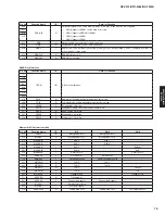
Serial Peripheral Interface (SPI)
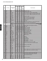
External Memory Interface
Pin No.
Function Name
I/O
Detail of Function
T18
R18
P17
P18
N15
N16
N17
N18
D[15:0]
I/O
Data bus for external memory and peripheral access.
M15
M16
M17
M18
L15
L16
L17
L18
E18
E17
E16
E15
D18
D17
D16
A[12:0]
O
Address bus for external memory and peripheral access.
C18
C17
C16
B18
A18
A17
F15
A13_RAS
O
SRAM: Address
output
SDRAM: Row access strobe
F16
A14_CAS
O
SRAM: Address
output
SDRAM: Column access strobe
F17
A15_BA0
O
SRAM: Address
output
SDRAM: Bank select
F18
A16_BA1
O
SRAM: Address
output
SDRAM: Bank select
G15
A17_DQM0
O
SRAM: Address
output
SDRAM: Data mask
G16
A18_DQM1
O
SRAM: Address
output
SDRAM: Data mask
H17
H16
H15
A[23:19]
O
Address bus for external memory and peripheral access.
G18
G17
Pin No.
Function Name
I/O
Detail of Function
D14
SPIDIN
I
SPI data receive.
D15
SPIDOUT
O
SPI data transmit.
B16
SPICLK
I/O
SPI clock.
Multi-master mode:
Chip-select input (used to detect bus conflict).
C15
SPINCS0
I/O
Master only mode:
Chip-select 1 output.
Slave mode:
Chip-select input.
Multi-master mode:
Chip-select 2 output.
B17
SPINCS1
I/O
Master only mode:
Chip-select 2 output.
Slave mode:
Not used.
74
RX-V475/HTR-4066/RX-V500D
RX-V475/HTR-4066/
RX-V50
0D
Summary of Contents for RX-V500D
Page 9: ...RX V500D A model RX V500D B G models 9 RX V475 HTR 4066 RX V500D RX V475 HTR 4066 RX V500D ...
Page 132: ... CONFIGURING THE SYSTEM SETTINGS RX V475 HTR 4066 RX V500D 133 ...
Page 133: ... システム設定を変更する RX V475 HTR 4066 RX V500D 134 ...
Page 146: ...147 RX V475 HTR 4066 RX V500D RX V475 HTR 4066 RX V500D MEMO ...
Page 147: ...RX V475 HTR 4066 RX V500D ...

