16
R-N402/R-N402D
R-N402/R-N402D
3.
T
he
USB
UPDATE
mode is activated and
“
USB
UPDATE
”
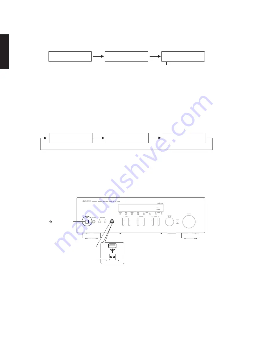
is displayed. Writing of the firmware starts automatically.
(Fig. 2)
Writing is started.
Writing being executed.
USB UPDATE
VERIFYING...
Sx-x:xx%
Fig. 2
* If error message is displayed during writing of the firmware, refer to
“
List of
E
rror Messages
”
to determine the
cause and perform the updating procedure again from the beginning.
4
. When writing of the firmware is completed,
“
UPDATE
SU
CC
ESS
”
,
“
P
L
EASE
...
”
and
“
P
OW
ER
OFF!
”
are displayed
repeatedly. (Fig. 3)
Writing is completed.
UPDATE SUCCESS
PLEASE...
POWER OFF!
Fig. 3
5
.
P
ress the
“
z
”
(
P
ower) key to turn off the power. (Fig.
4
)
6.
R
emove the
USB
storage device from the
USB
jack. (Fig.
4
)
7.
S
tart up the self-diagnostic function and check that the firmware version is the same as written ones.
(For details, refer to
“
Confirmation of firmware version
”
)
USB jack
USB storage device
“ ” (Power) key
Fig.4
S1: NET (Network module) section
S2: MAIN (IC301 on DIGITAL P.C.B.) section
S3: (Not for service)
S4: (Not for service)
S5: (Not for service)
Summary of Contents for R-N402
Page 3: ...3 R N402 R N402D R N402 R N402D FRONT PANELS R N402 R N402D ...
Page 4: ...4 R N402 R N402D R N402 R N402D REAR PANELS R N402 U model R N402 R model R N402 T model ...
Page 5: ...5 R N402 R N402D R N402 R N402D R N402 K model R N402 A model R N402 B G models ...
Page 6: ...6 R N402 R N402D R N402 R N402D R N402 L model R N402 S model R N402D B G models ...
Page 51: ...51 R N402 R N402D J I H G F E D C B A 1 2 3 4 5 6 7 Side B DIGITAL 1 Side B DIGITAL 2 ...
Page 60: ...60 R N402 R N402D MEMO MEMO ...
Page 82: ...83 R N402 R N402D R N402 R N402D MEMO ...
Page 83: ...R N402 R N402D ...


