background image

PW800W

5

: New Parts

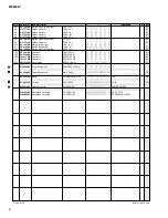
REF NO.

PART NO.

DESCRIPTION

REMARKS

QTY

RANK

RANK: Japan only

*
*
*

*
*
*
*

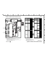
*
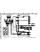
*

*
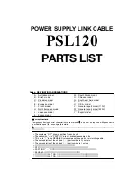
*
*

*

*

ELECTRICAL PARTS

PW800W

Circuit Board

AC (PWCOM)

(WB75820)(X4589B0)

Circuit Board

DC (PWCOM)

(WB75820)(X4589B0)

Circuit Board

LED (PWCOM)

(WB75820)(X4589B0)

Circuit Board

AC (PWCOM)

(WB75820)(X4589B0)

Circuit Board

DC (PWCOM)

(WB75820)(X4589B0)

Circuit Board

LED (PWCOM)

(WB75820)(X4589B0)

LED Spacer

LH-3-15

Bind Head Screw

3.0X10  MFZN2BL

2

01

Silicon Grease

G-746

(0412125)

Diode Spacer

GBPC2504

06

Jumper Wire

0.55

(VA07890)

C1

Capacitor

0.220 275V U.C.S

C2

Capacitor

0.220 275V U.C.S

C3

Capacitor

0.010 250V J.U.C.S

01

C5

Ceramic Capacitor-E

0.0047 500V M

01

C6

Ceramic Capacitor-E

0.0047 500V M

01

C7

Electrolytic Cap.-HD

220.00  35.0V

01

C8

Ceramic Capacitor-E

0.0047 500V M

01

C9

Ceramic Capacitor-E

0.0047 500V M

01

C10

Electrolytic Cap.

220.00  50.0V

C11

Electrolytic Cap.-HD

220.00  35.0V

01

C12

Ceramic Capacitor-F

0.0100  50V Z

01

C13

Electrolytic Cap.

4700  16.0V

02

C14

Capacitor

0.010 250V J.U.C.S

01

C15

Electrolytic Cap.

47.00  50.0V

01

C17

Capacitor

1000P 250V J.U.C.S

01

-20

Capacitor

1000P 250V J.U.C.S

01

C21

Monolithic Ceramic Cap.

0.100  50V Z

02

C22

Electrolytic Cap.

0.33  50.0V

01

C26

Ceramic Capacitor-B

1500P  50V K

01

C27

Electrolytic Cap.-HD

220.00  35.0V

01

CN2

Connector Base Post

PH  2P TE

01

CN6

Base Post Connector

VH  3P TE

01

CN7

Base Post Connector

VH  6P TE

01

CN8

Base Post Connector

VH  7P TE

01

CN9

Connector Base Post

PH  5P TE

01

CN10

Base Post Connector

VH  3P TE

01

CN11

Base Post Connector

VH  9P TE

01

CN12

Base Post Connector

VH 10P TE

02

CN13

Connector Base Post

PH  3P TE

01

CN14

Connector Base Post

PH  2P TE

01

CN15

Base Post Connector

VH  5P TE

01

CN16

Base Post Connector

VH  9P TE

01

CN17

Base Post Connector

VH 10P TE

02

CN18

Connector Base Post

PH  3P TE

01

CN19

Base Post Connector

VH  5P TE

01

CN21

Connector Base Post

PH  3P TE

01

D1

Diode

10EDA40-TA2B5 52

-3

Diode

10EDA40-TA2B5 52

D4

Diode

RL 10Z LFA4

01

D5

Diode

10EDA40-TA2B5 52

D6

Diode

10EDA40-TA2B5 52

D8

Diode

10EDA40-TA2B5 52

DB1

Diode Stack

S2VB20  2.0A 200V

03

DB2

Diode Stack

GBPC3504 35A 400V

07

F2

Fuse

T H 2.00A US 250V

IC1

IC

PQ1CG21H2FZ

REGULATOR

04

IC2

Photo Coupler

TLP421 GR

01

K1

Heat Sink

PUE16-25 P17.5 PN4

(WD27830)

K2

Heat Sink

T220M 25L

03

K3

Earth Plate

(WA20680)

K4

Fasten Tub

250 170267-1

01

-13

Fasten Tub

250 170267-1

01

K14

Earth Plate

(WA20680)

L1

Coil

SC-15-10J

L2

Coil

ELC10E391 390uH

04

LD1

LED Green

SLR-342MG3F

POWER Indicator

01

R1

Metal Oxide Film Resistor

2.2K  1W J

01

ELECTRICAL PARTS

(電気部品)

WB788700
WB788800
WB788900

WB788700
WB788800
WB788900
WC623400
EG330380

--

VM679600

--

V 9 9 0 8 3 0 0
V 9 9 0 8 3 0 0
V 3 3 1 1 6 0 0
FH223470
FH223470
WA163300
FH223470
FH223470
UR868220
WA163300
FG644100
UR739470
V 3 3 1 1 6 0 0
UR867470
V 7 6 8 2 4 0 0
V 7 6 8 2 4 0 0
V F 6 1 1 2 0 0
U I 5 6 5 3 3 0
FG613150
WA163300
VB389800
LB932030
LB932060
LB932070
VB390100
LB932030
LB932090
LB932100
VB389900
VB389800
LB932050
LB932090
LB932100
VB389900
LB932050
VB389900
WB880800
WB880800
V 4 0 9 6 3 0 0
WB880800
WB880800
WB880800
I H 0 0 1 1 2 0
VP591700
WC423800
XY455A00
V 8 1 0 0 5 0 0

--

BA808520

--

VD541800
VD541800

--

WD119300
VU096400
VR080300
VC748400

L E D ス ペ ー サ ー
+ バ イ ン ド 小 ネ ジ
シ リ コ ン グ リ ス
ダ イ オ ー ド ス ペ ー サ ー

規 格 認 定 コ ン M K P
規 格 認 定 コ ン M K P
規 格 認 定 コ ン   K H

セ ラ コ ン ( F )

規 格 認 定 コ ン   K H

規 格 認 定 コ ン   K H
規 格 認 定 コ ン   K H

セ ラ コ ン ( B )

コ ネ ク タ ベ ー ス ポ ス ト

コ ネ ク タ ベ ー ス ポ ス ト

コ ネ ク タ ベ ー ス ポ ス ト
コ ネ ク タ ベ ー ス ポ ス ト

コ ネ ク タ ベ ー ス ポ ス ト

コ ネ ク タ ベ ー ス ポ ス ト

ダ イ オ ー ド ス タ ッ ク
ダ イ オ ー ド ス タ ッ ク

ア ー ス プ レ ー ト
フ ァ ス ト ン タ ブ
フ ァ ス ト ン タ ブ
ア ー ス プ レ ー ト

コ イ ル   3 9 0 U H

酸 化 金 属 被 膜 抵 抗

Summary of Contents for PW800W

Page 1: ...ENSIONS 5 CIRCUIT BOARD LAYOUT 6 DISASSEMBLY PROCEDURE 7 CIRCUIT BOARDS 10 PARTS LIST OVERALL CONNECTOR CIRCUIT DIAGRAM OVERALL CIRCUIT DIAGRAM POWER SUPPLY PW800W Copyright c Yamaha Corporation All rights reserved 04 09 目次 総合仕様 パネルレイアウト 寸法図 ユニットレイアウト 分解手順 シート基板図 総コネクタ接続回路図 総回路図 200408 オープンプライス ...

Page 2: ...ou apply power to the unit WARNING CHEMICAL CONTENT NOTICE The solder used in the production of this product contains LEAD In addition other electrical electronic and or plastic Where applicable components may also contain traces of chemicals found by the California Health and Welfare Agency and possibly other entities to cause cancer and or birth defects or other reproductive harm DO NOT PLACE SO...

Page 3: ...ents DC PARALLEL INPUT DC OUTPUT 1 2 3 4 5 6 7 8 9 10 11 12 13 14 15 16 17 18 19 20 21 22 23 1 2 3 4 5 6 7 8 9 10 11 12 13 14 15 16 17 18 19 20 21 22 23 No Function No Function 1 24V 13 GND 2 24V 14 GND 3 24V 15 GND 4 24V 16 GND 5 24V 17 GND 6 24V 18 GND 7 24V 19 CAUTION 8 24V 20 CAUTION Ð 9 24V 21 DETECT A 10 GND 22 DETECT B 11 GND 23 DETECT GND 12 GND Frame GND 一般仕様 消費電力 1000W 外形寸法 W x H x D 480...

Page 4: ...OFF Switch q Front Panel フロントパネル Rear Panel リアパネル r e w t w DC OUTPUT Connector e DC PARALLEL INPUT Connector r AC IN Connector t GROUND Screw Terminal パネルレイアウト POWER ON OFF スイッチ DC OUTPUT コネクター DC PARALLEL INPUT コネクター AC IN 端子 アース用ネジ ...

Page 5: ...PW800W 5 DIMENSIONS 351 430 378 355 480 384 132 10 142 Units mm 寸法図 単位 ...

Page 6: ...Receptacle assembly レセプタクル Ass y Power transformer 電源トランス Front view DC AC LED Switch assembly Power switch スイ ッチAss y 電源スイ ッチ Power supply unit AC DC convertor 電源ユニット Window angle ウインドアングル CIRCUIT BOARD LAYOUT ユニットレイアウト ...

Page 7: ... Fig 1 7 Switch Assembly Power Switch Time required About 4 minutes 7 1 Remove the top cover See procedure 1 7 2 Remove the connector pins connected to K6 to K9 terminals of the AC circuit board 7 3 Remove the six 6 screws marked 330 and the four 4 screws marked 355 The front panel can then be removed Fig 1 7 4 Remove the switch assembly power switch by bending its claw Fig 1 8 Front Fan Motor Tim...

Page 8: ...EP600230 225 Bind Head Screw 3 0x8 MFZN2BL VB659000 230 Bind Head Screw 4 0x8 MFZN2BL EG340360 240 Bind Head Tapping Screw B 3 0x6 MFZN2BL EP600230 290 Bind Head Tapping Screw B 3 0x6 MFZN2BL EP600230 300 Pan Head Screw SP 4 0x20 MFZN2BL VB671600 310 Bind Head Tapping Screw B 3 0x6 MFZN2BL EP600230 317 Bind Head Tapping Screw B 3 0x6 MFZN2BL EP600230 330 Oval Head Screw 4 0x8 MFZN2BL VS153600 355 ...

Page 9: ...1 Remove the top cover See procedure 1 10 2 Remove the screw marked 480A The ground wire can then be removed Fig 2 10 3 Remove the four 4 screws marked 140A The receptacle assembly DC OUTPUT can then be removed Fig 2 10 4 Remove the four 4 screws marked 140B The receptacle assembly DC PARALLEL INPUT can then be removed Fig 2 11 AC Inlet Assembly Time required About 2 minutes 11 1 Remove the top co...

Page 10: ...ALLEL INPUT to DC OUTPUT to Power Supply Unit CN2 to Power Switch to Power Transformer to AC Inlet to Power Supply Unit CN1 Primary CIRCUIT BOARDS シート基板図 DC Circuit Board Component side 部品側 AC Circuit Board 2NAP WB75820 01 4 ...

Page 11: ... 部品側 LED Circuit Board A A to DC PARALLEL INPUT to DC OUTPUT to Power Supply Unit CN2 to Power Supply Unit CN6 to Power Transformer to FAN Rear L to FAN Rear R to FAN Front POWER Secondary Component side 部品側 2NAP WB75820 01 4 ...

Page 12: ...ot available as spare parts This mark in the REMARKS column means these parts are interchangeable The second letter of the shaded part number is O not zero The second letter of the shaded part number is I not one 印の部品は 安全を維持するために重要な部品です 交換する場合は 安全のために必ず指定の部品をご 使用ください 部品価格ランクは 変更になることがあります QTY欄に記されている数字は 各ユニット当たりの使用個数です PART NO が の部品は サービス用部品として準備されておりません REMARKS欄の マークの部品は 併用部品です 網掛けの付いたPART NO の2番...

Page 13: ...5 140 140 110 110 480 480 110 100 150a 145 160 150 20 30 50 80 80 170 356 357 180 180 80 40 210 315 317 230 230 240 240 240 250 270 270 310 460 310 310 310 290 260 270 225 230 215 440 440 440 440 280 220 70 110 90 110 120 320 360 370 360 370 490 340 340 350 350 355 330 330 330 330 80 310 300 440 440 150 135 130 ...

Page 14: ...PW800W 3 550 130 130 130 135 135 135 90 530 520 510 490 560 520 510 510 510 490 450 450 135 150 130 450 450 440 440 530 560 440 440 440 450 450 500 500 Bottom side ボトム側 Bottom side ボトム側 Top view ...

Page 15: ...ng Screw B 4 0X8 MFZN2BL 14 01 400 Label WC30600 440 Cord Binder S 14B 6 03 450 Cord Holder BK 1 11 01 460 Insulation Sheet BFG 20AD 02 480 Bind Head Screw 4 0X8 MFZN2BL 2 01 490 Switch Assembly SW FASTON POWER ON OFF 500 Connector Assembly ADA1K 6P 510 Connector Assembly ADA1K 10P VH 6P 7P 520 Connector Assembly ADA1K 3P PH 5P 530 Connector Assembly PH PH 2P 400L 550 Clamp Filter ZCAT3035 1330 07...

Page 16: ...TA2B5 52 D4 Diode RL 10Z LFA4 01 D5 Diode 10EDA40 TA2B5 52 D6 Diode 10EDA40 TA2B5 52 D8 Diode 10EDA40 TA2B5 52 DB1 Diode Stack S2VB20 2 0A 200V 03 DB2 Diode Stack GBPC3504 35A 400V 07 F2 Fuse T H 2 00A US 250V IC1 IC PQ1CG21H2FZ REGULATOR 04 IC2 Photo Coupler TLP421 GR 01 K1 Heat Sink PUE16 25 P17 5 PN4 WD27830 K2 Heat Sink T220M 25L 03 K3 Earth Plate WA20680 K4 Fasten Tub 250 170267 1 01 13 Faste...

Page 17: ...iode MTZJ8 2B 8 2V 01 Power Supply Unit ADA1000F 24 YMH Power Transformer H B E INDI 09 Motor DC KDE1208PTS3 6 Fan 3 09 AC Inlet 3P M1908 C AC IN 03 Switch Assembly SW FASTON POWER ON OFF Receptacle Assembly VH 5P 9P 10P DC OUTPUT Receptacle Assembly VH 5P 9P 10P DC PARALLEL INPUT VC748400 HF757100 HF757100 HF755560 HF757100 VC754700 HF757220 VC326700 VC328800 VC746800 VE198700 VC614000 IC1815M0 I...

Page 18: ...LLEL INPUT 丸型コネクタ NOTE Pin on the same line are connected to each other 同一のピン同士が接続されます 接続がないピンについては 上記に表していません Pins which are not to be connected are not shown above 内はパネル上の印字を示します Characters in the brackets indicate the printing on the panel NOTE Characters in the brackets indicate the printing on the panel 内はパネル上の印字を示します 印部分の接続は右側に詳細を示します その他の接続はコネクタの両端で全ピン1対1の対応です Double reference marks indicat...

Page 19: ... Film Resistor 酸化金属被膜抵抗 セ Ceramic Capacitor セラコン 28CC1 8831318 4 Note See parts list for details of circuit board component parts 注 シートの部品詳細はパーツリストをご参照ください When PM5D or PM5D RH is connected adjust VR601 on the power supply unit so that the output voltage becomes 24 5V 0 5V PM5DまたはPM5D RHを接続した場 合 出力電圧が 24 5V 0 5 Vになる ように電源ユニットのVR601を調整し ます PQ1CG21H2FZ XY455A00 REGULATOR DC IC1 1 V in 2 V out 3 COM ...

Page 20: ...as spare parts This mark in the REMARKS column means these parts are interchangeable The second letter of the shaded part number is O not zero The second letter of the shaded part number is I not one 印の部品は 安全を維持するために重要な部品です 交換する場合は 安全のために必ず指定の部品をご 使用ください 部品価格ランクは 変更になることがあります QTY欄に記されている数字は 各ユニット当たりの使用個数です PART NO が の部品は サービス用部品として準備されておりません REMARKS欄の マークの部品は 併用部品です 網掛けの付いたPART NO の2番目の文字は ゼロ ではなく...

Page 21: ...LETE ASSEMBLY PSL120 Complete Assembly J WD19450 Complete Assembly Y WD19460 30 DC Power Supply Cable UL2464 16X24 L 1200 50 Label PW CABLE WD25510 New Parts RANK Japan only パーツリスト PSL120 WD197700 部 品 名 同 梱 品 セ ッ ト 同 梱 品 セ ッ ト 同 梱 品 セ ッ ト 電 源 ケ ー ブ ル ラ ベ ル PW800W PW800W ...

Reviews: