background image

TROUBLESHOOTING

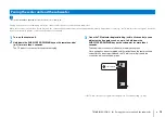
Pairing the center unit and the subwoofer

En

75

• Be sure that “WIRELESS FUNCTION” in the setup menu is set to “ON” (p. 56).

Pairing is the process of establishing a wireless connection between the center unit and subwoofer.

When the center unit is turned on for the first time, the center unit and subwoofer are usually paired automatically. If a problem occurs (e.g., the TX indicator does not glow), follow the 
instructions below to pair the center unit and subwoofer manually.

1

Turn on the center unit.

2

Hold down the SUBWOOFER PAIRING key on the remote control 
(p. 9) 
for more than 3 seconds.

The TX indicator on the center unit will blink rapidly.

3

Once the TX indicator begins blinking (within 30 seconds), use an 
object with a fine point, such as a pin, to hold down the 
SUBWOOFER PAIRING key on the subwoofer for more than 3 
seconds.

The subwoofer’s connection indicator will rapidly blink green.

Once pairing has been completed and the link between the center unit and 
subwoofer has been re-established, the TX indicator will glow and the 
connection indicator will glow green.

If the TX indicator does not glow after pairing, see “Troubleshooting (p. 69).

Pairing the center unit and the subwoofer

INPUT

SYSTEM CONNECTOR

SUBWOOFER PAIRING

SUBWOOFER PAIRING

Summary of Contents for NS-WSW120

Page 1: ...Digital Sound Projector Owner s Manual Read the supplied booklet Safety Brochure before using the unit English ...

Page 2: ...splaying the menu screen on the TV 30 Selecting the language for menu display 31 Auto setup for appropriate surround effects IntelliBeam 32 Installing the IntelliBeam microphone 32 Using AUTO SETUP IntelliBeam 33 Operating the unit by TV s remote control HDMI control 37 What is the HDMI control function 37 Setting the HDMI control function 38 Changing the connection method and connected devices 38...

Page 3: ...STEM 62 Settings each input source Option menu 63 Setting the option menu 63 Option menu list 64 Adjusting tones TREBLE BASS 64 Adjusting input level of each jack VOLUME TRIM 64 Audio delay control AUDIO DELAY 64 Assigning HDMI audio to a different input jack AUDIO ASSIGN 64 Advanced setup 65 Setting the advanced setup 65 Advanced setup list 66 TROUBLESHOOTING 67 Troubleshooting 67 General 67 Blue...

Page 4: ... TV remote control Sound beams are reflected off walls using unique real surround sound formats and techniques allowing listeners to enjoy their preferred acoustic environment Automatically and quickly adjusts surround sound effects for the listening room setup IntelliBeam p 32 Reproducing stereo or multichannel sounds with the sound fields like actual movie theaters and concert halls CINEMA DSP p...

Page 5: ...using the remote control indicates supplementary explanations for better use indicates precautions for use of the unit and its feature limitations Supplied accessories Center unit YSP CU2500 Wireless subwoofer NS WSW120 Remote control Batteries AAA R03 UM 4 x2 Optical cable 1 5 m 4 9 ft IntelliBeam microphone 6 m 19 7 ft Cardboard microphone stand Non skid pads 8 pcs Owner s Manual CD ROM Quick Re...

Page 6: ...urns off Power off 4 Front panel display Shows information about the operational status of this unit p 8 5 PHONES jack For connecting the headphones p 44 6 INTELLIBEAM MIC jack For connecting the supplied IntelliBeam microphone p 33 7 INPUT key Selects the playback device p 39 8 VOLUME keys Adjusts the volume of the unit p 39 9 z key Turns on off the unit When the unit is turned off this unit cons...

Page 7: ...an optical digital audio output jack p 25 26 6 HDMI OUT ARC jack For connecting to an HDMI compatible TV and outputting video audio signals p 25 7 HDMI IN 1 3 jacks For connecting an HDMI compatible playback device such as a BD DVD player a satellite and cable TV tuner and a game console p 26 8 TV Remote Repeater Receives signals from a TV remote control via the front of the center unit and transm...

Page 8: ...tor Glows when the TV Remote Repeater function is enabled p 15 8 TX indicator Glows while the wireless connection to the subwoofer is being established p 29 9 VOL indicator Indicates the current volume level p 39 0 CINEMA DSP indicator Glows when a CINEMA DSP program is selected p 40 A Multi information display Displays an input source and surround information p 46 Displays settings and informatio...

Page 9: ...E key Turns the UniVolume function on or off p 46 C ENHANCER key Turns Compressed Music Enhancer to on or off p 45 D REPEATER key Turns the TV Remote Repeater function on or off p 15 E z key Turns on off the unit p 39 F BEAM key Switches the sound beam output method p 42 G TARGET key Switches to target playback mode p 44 H CLEAR VOICE key Turns the CLEAR VOICE function on or off p 45 I CH LEVEL ke...

Page 10: ... to the center unit using a wired connection p 29 4 SUBWOOFER PAIRING key Used to pair the center unit with the subwoofer manually p 75 Use a pin or other pointed object to press this key 5 Heat discharge unit Discharges heat generated inside the subwoofer Do not cover the heat discharge unit 6 Power cable For connecting to an AC wall outlet p 28 Subwoofer INPUT SYSTEM CONNECTOR SUBWOOFER PAIRING ...

Page 11: ...ives or similar devices near the subwoofer Do not stack the center unit and subwoofer directly on top of other playback devices or vice versa Heat and vibrations may result in damage or malfunction Recommended place for installation Center unit Subwoofer Use the TV Remote Repeater function if the center unit obstructs the remote control sensor on the TV p 15 If the center unit cannot be installed ...

Page 12: ... the left and right corners Corner installation Install this unit in the corner at a 40 to 50 angle from the adjacent walls Parallel installation Install this unit as close to the exact center of the wall as possible Ideal installation condition Install this unit as close to the exact front of your normal listening position as possible The distance between listening position and the unit should be...

Page 13: ...ted off the walls If this unit cannot be repositioned or the listening position cannot be changed the optional YRB 100 sound reflection board may be installed for a better surround sound experience p 73 Irregularly shaped rooms with solid walls on all sides Irregularly shaped rooms that are open to a hallway on one side ...

Page 14: ...m The surround sound effects produced by this unit may not be sufficient when this unit is installed in the following locations Rooms with walls inadequate for reflecting sound beams Rooms with acoustically absorbent walls Rooms with measurements outside the following range W 3 to 7 m 10 to 23 ft H 2 to 3 5 m 7 to 11 5 ft D 3 to 7 m 10 to 23 ft Rooms where objects such as furniture are likely to o...

Page 15: ...te control is using infrared signals 1 Turn on the unit 2 Hold down the REPEATER key on the supplied remote control for more than 3 seconds to enable the TV Remote Repeater function The REPEATER indicator on the front panel display will glow Disabling the TV Remote Repeater function Hold down the REPEATER key on the supplied remote control for more than 3 seconds If the TV remote control does not ...

Page 16: ...nts inner legs that are fixed to the center unit with screws and components outer legs that can be removed by rotating them 1 Remove the outer legs Keep turning the outer legs counter clockwise to remove them 2 Remove the inner legs Use a screwdriver to remove the screws 3 Attach the one of the four supplied non skid pads at each of the four corners on the bottom of the center unit An example of p...

Page 17: ...n them points toward the rear side and insert the protrusions into the slots on the center unit Use a screwdriver to tighten the screws and lock the inner legs in place 2 Attach the outer legs Position the outer legs so that the arrow U on them points towards the rear side and turn them clockwise to attach them Rear side ...

Page 18: ...s Store the legs screws and washers in a safe place out of the reach of children for later use and to prevent children from accidentally swallowing screws or washers 2 Place the subwoofer on its side as shown in the illustration and attach each of the four supplied pads at each of the four corners 3 Position the subwoofer as shown in the illustration Positioning the subwoofer on its side Leg Washe...

Page 19: ...not be available in some countries or regions Space between this unit and the wall is limited Therefore use of a flexible HDMI cable or right angle connector neither supplied is strongly recommended Mounting the SPM K20 Be sure that there is enough space on the wall to mount the wall mount bracket and this unit Follow the instructions below to mount both 1 Attach the three supplied pads to the wal...

Page 20: ... center of the TV The wall mount bracket is designed to be offset slightly to the right of the center of this unit Once screw position has been marked remove the template Screw self tapping screws not supplied partway into the wall where marked using the template Mount the wall mount bracket on these screws and then tighten the screws Screw self tapping screws at least six including the two previo...

Page 21: ...ng the screws also supplied with this unit Do not tighten the screws until this unit has been mounted on the wall mount bracket 5 Connect commercial cables to this unit 6 Mount this unit on the wall Insert the screws on this unit into the mounting holes on the left and right sides of the wall mount bracket and then slide this unit to the left When mounting or removing it hold this unit firmly with...

Page 22: ...ten screws Tighten the screws used to attach the spacer to this unit in step 4 Dimensions 10 8 28 125 154 3 mm YSP CU2500 SPM K20 mm mm 457 500 298 3 276 8 944 YSP CU2500 SPM K20 1 4 kg 5 13 5 188 3 166 8 33 5 54 51 125 16 7 10 8 143 153 8 ...

Page 23: ...ote control be sure to read battery and remote control precautions in Safety Brochure separate booklet Installing the batteries Battery 2 AAA R03 UM 4 Press down on the arrow and slide the cover in the direction in which it points Slide the cover back to close it Operation range STATUS Within 6 m 20 ft ...

Page 24: ... inserting the cable plug Doing so may damage the cable plug and or jack STATUS PHONES INTELLIBEAM MIC Audio connection Video connection Audio and video connection This unit Plays audio from TV broadcasts BD DVD discs etc Game console HDMI compatible Satellite and cable TV tuner not HDMI compatible TV Plays video from TV broadcasts BD DVD player etc BD DVD player HDMI cable HDMI cable HDMI cable O...

Page 25: ...o content from the TV can be input via the AUX2 coaxial digital or AUX1 analog jack Set TV INPUT in the setup menu to COAXIAL AUX2 or ANALOG AUX1 accordingly p 60 TVs that support Audio Return Channel ARC Audio Return Channel ARC ARC enables input and output of audio signals via a single HDMI cable If the TV supports ARC audio signals from the TV can be input to this unit via the same HDMI cable u...

Page 26: ...I logo printed on it A cable with a maximum length of 5 m is recommended to prevent degradation of signal quality Use an ARC compatible HDMI cable For playback of 3D and 4K video content use a high speed HDMI cable Connect a video device to this unit via the optical cable Next connect the video device s video output to the TV s video input If you switch the input source to the OPTICAL jack by pres...

Page 27: ...eo input If you switch the input source to the AUX1 jacks by pressing the AUX1 key the audio played back on the video device will be output from the unit Coaxial connection SYSTEM CONNECTOR R L AUX1 AUX2 TV OPTICAL OUT ARC IN1 IN2 HDMI IN3 SUBWOOFER OUT COAXIAL AUX2 C C Center unit rear AUX2 coaxial digital jack Audio output coaxial digital Video device TV To video output jack To video input jack ...

Page 28: ...nections En 28 Plug in the power cable of the center unit and the subwoofer Connecting the power cable INPUT SYSTEM CONNECTOR SUBWOOFER PAIRING Center unit rear To an AC wall outlet Subwoofer rear To an AC wall outlet ...

Page 29: ...reen If there is no sound coming out of the subwoofer or if sounds is intermittent connect the center unit and subwoofer via an RCA mono cable and system control cable 3 5 mm monaural mini plug cable A system control cable 3 5 mm monaural mini plug cable is required to turn the center unit and subwoofer on and off at the same time To connect the center unit and subwoofer using a wired connection s...

Page 30: ...n the TV is receiving HDMI signals the menu is superimposed over video content Press the SETUP key or OPTION key a second time to cancel menu display The setup menu p 51 can only be displayed on a TV screen It cannot be shown in the front panel display Initial settings TV remote control example Switch input sources SYSTEM CONNECTOR R L AUX1 AUX2 TV OPTICAL OUT ARC IN1 IN2 HDMI IN3 SUBWOOFER OUT IN...

Page 31: ... is not displayed Confirm the following cases The HDMI input jack of your TV and the HDMI OUT ARC jack of the unit are connected The input of your TV is set to HDMI 1 example 4 Press the S T key to select the desired language Settings ENGLISH default DEUTSCH FRANÇAIS ESPAÑOL ITALIANO NEDERLANDS РУССКИЙ SVENSKA TÜRK 5 Press the SETUP key to exit the setup menu OSD LANGUAGE ENGLISH DEUTSCH FRANÇAIS ...

Page 32: ... inaccurate sound optimization 1 Place the IntelliBeam microphone at your normal listening position Assembling the supplied cardboard microphone stand Use the supplied cardboard microphone stand or a tripod to place the IntelliBeam microphone at the same height as your ears would be when you are seated Position the IntelliBeam microphone so that it is parallel with the floor Make sure that there a...

Page 33: ...ng in improper measurement 4 Press the ENTER key to start the AUTO SETUP procedure and then leave the room within 10 seconds The screen automatically changes during the AUTO SETUP procedure If the AUTO SETUP procedure is complete this unit rings the chimes Using AUTO SETUP IntelliBeam PHONES INTELLIBEAM MIC INTELLIBEAM MIC IntelliBeam microphone Cardboard microphone stand A U T O S E T U P P R E P...

Page 34: ...ting you to begin measurement again Press the ENTER key to begin measurement again See page 47 for more information on the system memory function 6 Remove the IntelliBeam microphone The AUTO SETUP COMPLETE screen closes The IntelliBeam microphone is sensitive to heat so should not be placed anywhere where it could be exposed to direct sunlight or high temperatures such as on top of AV equipment AU...

Page 35: ...menu appears BEAM SOUND OPTIMIZE Select this optimization feature if you make settings for the first time This menu takes about 3 minutes BEAM OPTIMIZE ONLY Use to optimize the beam angle so that the parameter best matches your listening environment This menu takes about 1 minute SOUND OPTIMIZE ONLY Use to optimize the beam delay volume and quality so that the parameters best match your listening ...

Page 36: ...Please re try The IntelliBeam microphone is not placed in front of this unit Position the IntelliBeam microphone in front of this unit and begin measurement again ERROR E 5 Please check MIC position MIC should be set above 1 8m 6 0ft and re try The IntelliBeam microphone is not placed in the right distance from this unit Position the IntelliBeam microphone at a distance of more than 1 8 m 6 0 ft f...

Page 37: ... operations configure HDMI control settings p 38 With some TVs the following additional functions can be controlled Turning the UniVolume function on and off Navigating this unit s menus displayed on the TV Even if your TV supports the HDMI control function some functions may not be available For details refer to the manual supplied with your TV We suggest using devices TV BD DVD player etc from t...

Page 38: ...DMI control function of the TV and BD DVD player turn off all connected devices and change the connections 2 Perform steps 1 to 7 of Setting the HDMI control function Setting the HDMI control function HDMI1 Input source name If the HDMI control function is not working Be sure that all devices are correctly connected to this unit and that settings are properly configured as described below HDMI CON...

Page 39: ...om both TV speaker and this unit mute the TV sound When sound input to HDMI IN jack is output from the TV the volume level does not change even if you press the VOL key or the MUTE key To mute the sound press the MUTE key The VOL indicator in the front panel display blinks To resume the volume press the MUTE key again or press the VOL key The subwoofer volume can be adjusted separately from the wh...

Page 40: ...e CINEMA DSP technology reproduces sound fields sound amplitudes for optimal surround sound playback 1 Press the CINEMA DSP MOVIE MUSIC or ENTERTAINMENT key repeatedly to select the desired program The CINEMA DSP category name appears in the front panel display and the CINEMA DSP indicator p 8 glows The CINEMA DSP programs are not available in the following conditions Audio signals with sampling f...

Page 41: ... Club This program recreates the acoustic environment of The Bottom Line a famous jazz club in New York once and lets you feel as if you are seated right in front of the stage Sports This program reproduces the energetic environment of live sports broadcasting converging a commentator s voice on the center and broadening the overall atmosphere of the stadium and lets you feel as if you are seated ...

Page 42: ...tput setting is AUTO p 55 At the default setting sounds are output from the appropriate number of channels according to input signal as indicated below With 2 5 1 channel input 5 1 channel output With 6 1 7 1 channel input 7 1 channel output The output method can be locked at 5 1 or 7 1 channel output SURROUND is displayed when headphones are used Switching between sound beam output methods is not...

Page 43: ... center and surround right and left channels ST 3BEAM 2 Stereo 3 Beam Plus 2 Outputs normal sound from the front right and left channels and sound beams from the center and surround back right and left channels Surround left channel sources are mixed with front left and surround back left channel sources Surround left channel content is generated from the front left and surround back left channels...

Page 44: ...ch time the X key is pressed A maximum angle of 90 degrees in either direction is possible Disabling target playback mode Press the SURROUND key or STEREO key to turn target playback mode off The CINEMA DSP programs are not available in target playback mode Bass output is controlled to prevent sounds from spreading in other directions Enjoying surround sound with headphones Plug the headphones int...

Page 45: ...nd sports commentary are played back very clearly 1 Press the CLEAR VOICE key to turn on the CLEAR VOICE function Press the key again to turn off the function Adjusting volume for each channel Adjust the volume of playback for each channel audio in each direction so that sounds are evenly distributed in their respective directions Refer to CHANNEL LEVEL p 56 when adjusting the volume of each chann...

Page 46: ...key ECO ON is displayed and the front panel display turns off The brightness of STATUS indicator is minimized Disabling the Eco function Press the ECO key ECO OFF is displayed in the front panel display Disable this function for louder playback When this function is enabled DIMMER in the setup menu p 60 and MAX VOLUME in the advanced setup menu p 66 cannot be configured Switching information displ...

Page 47: ...ettings configured for parties The following settings can be saved to system memory IntelliBeam measurement results p 33 See page 34 for instructions on saving measurement results for IntelliBeam When HORIZONTAL ANGLE BEAM TRAVEL LENGTH FOCAL LENGTH and IMAGE LOCATION are configured in the setup menu p 51 these settings are applied to IntelliBeam s AUTO SETUP measurements Surround playback p 40 st...

Page 48: ...s selected as the input 2 Turn on the Bluetooth device to be paired and perform pairing The operation varies depending on the device Refer to the instruction manual supplied with the device 3 Select YSP 2500 Yamaha in the Bluetooth device list on the device If a passkey PIN is required enter the number 0000 When pairing is completed or a completion message appears on the Bluetooth device Listening...

Page 49: ...nt panel display 3 Play back a song on the Bluetooth device Perform Bluetooth connection with the device and unit within 10 m 33 ft of each other It may be necessary to select YSP 2500 Yamaha in the Bluetooth device list again in the event that a connection problem occurs You may have to change the output setting to output audio to the unit depending on the Bluetooth device you are using Adjust th...

Page 50: ...n 3 seconds Using the HOME THEATER CONTROLLER app By installing the dedicated free app HOME THEATER CONTROLLER to a Bluetooth device such as a smartphone you can perform various operations easily and conveniently with the Bluetooth device Setting items basic operation sound field program sound adjustments For details on HOME THEATER CONTROLLER see the product information on our website BT STANDBY ...

Page 51: ...he SETUP key Hold down the SETUP key to display OSD LANGUAGE directly on the screen p 31 61 2 Press the S T key to select a menu and then press the X key or ENTER key Repeat these steps to display the desired menu Press the W key or RETURN key to return to the previous menu 3 Press the S T key to change the setting value of each menu 4 Press the SETUP key again to exit the setup menu Setup menu SE...

Page 52: ...6 DISTANCE Specify the distance from the subwoofer to the listening position 56 SOUND CHANNEL LEVEL Front L Front R Center Surround L Surround R Subwoofer Adjusts the volume of each channel 56 Adaptive DRC Choose whether or not dynamic range is adjusted based on this unit s volume level 57 DYNAMIC RANGE Specify dynamic range 57 MATRIX DECODER Specify a surround decoder 58 Dolby PLIIx PARAMETER Cen...

Page 53: ...audio output methods for surround playback p 42 Specify the distance that sound beams travel for each channel The distance starts at this unit ends at the listening position and includes refraction off a wall The audio delay is adjusted and sound from each channel arrives at the listening position simultaneously Item Front L Front R Center Surround L Surround R Control range 0 3 m to 24 0 m 1 0 ft...

Page 54: ...trol range 1 0 m to 13 0 m default 0 5 m 3 5 ft to 43 5 ft default 1 5 ft We recommend using the default setting 0 5 m or 1 5 ft for Center Channels that cannot be configured are displayed in grey as settings are specified as indicated in Switching between audio output methods for surround playback p 42 AUTO SETUP p 33 automatically enables a range for optimal listening sweet spot that is broader ...

Page 55: ...e higher the percentage the louder the output from the center channel Once ADJUSTMENT has been set to ON this setting can be selected Control range 0 default to 95 Specify the sound beam output method 5 1ch 7 1ch AUTO Settings The available sound beam output methods vary depending upon the current CHANNEL OUT setting p 42 IMAGE LOCATION SETUP MENU BEAM IMAGE LOCATION OFF default No adjustments are...

Page 56: ...l to balance output levels Use test sounds output from each channel to adjust volume for optimal balance Item Front L Front R Center Surround L Surround R Subwoofer Adjustable range 20 to 20 When the sound beam output method is set to MY SUR My Surround with the BEAM key the following items can be configured Center Surround L R Subwoofer SUBWOOFER SETUP MENU BEAM SUBWOOFER OFF Select to connect th...

Page 57: ...en the UniVolume function is enabled Adjust this unit s dynamic range difference between maximum and minimum volumes Settings Adaptive DRC is automatically set to OFF when the settings other than Max is selected Adaptive DRC SETUP MENU SOUND Adaptive DRC OFF The dynamic range is not adjusted automatically ON default Adjust the dynamic range automatically On Output level Output level Off Off Input ...

Page 58: ... surround decoder for playback of 5 1 channel sources When CHANNEL OUT p 55 is set to 7 1ch this unit decodes 5 1 channel sources and then playback them in up to 7 1 channel surround One of the following decoders is automatically selected depending on the input signals MATRIX DECODER SETUP MENU SOUND MATRIX DECODER PLII Movie default Use the Dolby Pro Logic II decoder suitable for movies PLII Musi...

Page 59: ...s Adjustable range 3 to 3 default 0 HDMI setup Use to configure the settings related to HDMI signals and the HDMI control function Turn HDMI control p 37 on or off Settings This setting can be configured only when HDMI CONTROL is set to OFF Use to select a device to play back HDMI audio signals Settings When HDMI CONTROL is set to ON select the audio output device based on the settings configured ...

Page 60: ...is pressed If this unit s input source is switched to ANALOG AUX1 Audio is input from the device TV connected to the AUX1 analog jack on this unit when the TV key is pressed Audio is input from the device connected to the TV optical jack on this unit when the AUX1 key is pressed DISPLAY settings Adjust the brightness of the front panel display The smaller the value the dimmer the display Settings ...

Page 61: ...setting for U S A and Canada models If the unit used with measurement displays is changed from METERS to FEET or vice versa configure settings again to reflect the change in unit The change will not be reflected with current settings OSD LANGUAGE SETUP MENU DISPLAY OSD LANGUAGE Menus are displayed in Japanese ENGLISH default Menus are displayed in English DEUTSCH Menus are displayed in German FRAN...

Page 62: ...FORMATION AUDIO Format Digital audio format Number of channels The number of channels contained within the input signal front surround low field effects LFE Example 3 2 0 1 means signal contains 3 front channels 2 surround channels and LFE If the signal contains channels other than front surround and LFE the total number of channels may be displayed Example 5 1ch Sampling frequency The sampling fr...

Page 63: ...tor key for the input source to be configured 2 Press the OPTION key 3 Select the items by pressing the S T key then press the X key or ENTER key 4 Change setting value by pressing the S T key 5 Press the OPTION key to exit the option menu The configurable items vary depending on the input source selected Settings each input source Option menu OPTION TREBLE BASS VOLUME TRIM AUDIO DELAY AUDIO ASSIG...

Page 64: ...tching video of the BD DVD player Settings HDMI default OPTICAL AUX2 While the AUX2 coaxial jack is the default AUX2 setting sound is input as follows depending upon the setting specified for TV INPUT p 60 in the setup menu TV INPUT set to OPTICAL TV default When AUX2 is selected sound is input from the AUX2 coaxial jack TV INPUT set to COAXIAL AUX2 When AUX2 is selected sound is input from the TV...

Page 65: ...trol to turn on the power ADVANCED appears in the front panel display The advanced setup menu is not displayed on the TV screen 3 Release the INPUT key on the top panel 4 Press the S T key to display the desired menu in the front panel display and then press the X key or ENTER key To return to the previous menu press the W or RETURN key 5 Press the S T key to change setting 6 Press the z key to tu...

Page 66: ...ction board is not used default Use the YRB 100 sound reflection board for the front left channel Refer to page 73 for details of YRB 100 YRB FR YES The reflection board is used NO The reflection board is not used default Use the YRB 100 sound reflection board for the front right channel Refer to page 73 for details of YRB 100 YRB SL YES The reflection board is used NO The reflection board is not ...

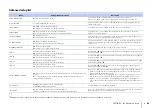
Page 67: ...om the outlet and plug it again in after 30 seconds This unit is suddenly turned off The internal temperature becomes too high and the overheat protection circuitry has been activated Wait for about 1 hour for this unit to cool down turn it back on after confirming an adequate amount of ventilation space and not to cover this unit with a cloth 11 When the Auto Power Standby function is enabled thi...

Page 68: ...r than the TV s built in speakers No sound or too small sound from a specific channel The output level of the channel is muted Raise the output level of the channel 45 56 The beam setting is inappropriate Adjust the beam setting 32 The source is played in stereo playback mode Switch to surround playback mode 40 Some audio output methods do not output sound beams for certain channels Switch the sou...

Page 69: ...s communication Move this unit away from devices such as microwave ovens or wireless network devices that emit electromagnetic waves Use cables to connect the subwoofer to the center unit 29 The TX indicator on the center unit blinks and the connection indicator on the subwoofer glows red or continuously blinks red The center unit and subwoofer are not paired Pair the center unit and subwoofer If ...

Page 70: ...t is not displayed The input switch of TV is not set correctly Set the TV s input source to this unit 30 A digital or high frequency equipment produces noises The unit may be placed close to digital equipment or high frequency equipment Move the equipment away from the unit The HDMI control function does not work properly HDMI CONTROL is set to OFF Set HDMI CONTROL to ON 59 The HDMI control functi...

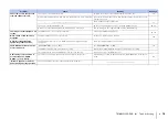
Page 71: ...e multiple Bluetooth connections Terminate current Bluetooth connection and make connection for the desired device 49 More than nine devices are paired and the oldest pairing information is deleted Perform pairing again The unit can retain pairing information for up to eight devices When pairing a ninth device the oldest pairing information will be deleted 48 No sound is produced or the sound is i...

Page 72: ...e TV Remote Repeater function cannot be used Move the center unit so that it does not block the remote control sensor on the TV and use the TV s remote control to operate the TV The center unit and TV are too close together or too far apart Move the center unit to adjust the distance between the TV Remote Repeater and the TV remote control sensor If necessary adjust the height of the center unit 1...

Page 73: ...ure Always hold the pole when moving the sound reflection board Use CHANNEL LEVEL in the setup menu p 56 to determine the precise direction from which sounds are difficult to hear When surround effect is not enough Figure 1 Ideal condition Figure 2 Surround right beam is not being reflected because there is no wall Surround right is quieter than surround left or surround right is in front of its p...

Page 74: ...urn this unit off Press it a second time to turn this unit on again 6 Plug the IntelliBeam microphone into this unit and then perform AUTO SETUP BEAM SOUND OPTIMIZE from the IntelliBeam menu p 33 Be sure that the channels FL FR SL and SR configured for the sound reflection board are displayed for YRB on the SHOW RESULT screen An asterisk is displayed with a channel exhibiting poor sound beam refle...

Page 75: ...BWOOFER PAIRING key on the remote control p 9 for more than 3 seconds The TX indicator on the center unit will blink rapidly 3 Once the TX indicator begins blinking within 30 seconds use an object with a fine point such as a pin to hold down the SUBWOOFER PAIRING key on the subwoofer for more than 3 seconds The subwoofer s connection indicator will rapidly blink green Once pairing has been complet...

Page 76: ...A digital sound projector outputs sound beams from five channels including front left right center and surround left right channels by reflecting these beams off of walls so that sounds reach the listener from the appropriate direction It features a technology that enables true surround sound without requiring the installation of speakers in front of or behind the listener By combining front and s...

Page 77: ...sounds that are identical bit for bit to studio masters for a great home theater experience It delivers up to 8 discrete channels of 24 bit 96 kHz up to 6 discrete channels of 24 bit 192 kHz audio simultaneously and is widely used with Blu ray Discs DTS Digital Surround This is a compressed audio format for 5 1 channels developed by DTS It is widely used with DVD discs DTS Express This is a compre...

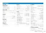
Page 78: ...luetooth Standby ON Less than 1 2 W HDMI CONTROL OFF and Bluetooth Standby ON Less than 0 5 W HDMI CONTROL OFF and Bluetooth Standby OFF Less than 0 4 W Dimensions W H D When the legs are adjusted to a minimum height 944 73 144 mm 37 1 8 2 7 8 5 5 8 in Weight 4 0 kg 8 8 lbs NS WSW120 Driver 10 cm 4 in cone woofer 2 non magnetic shielding type INPUT jack 1 SYSTEM CONNECTOR jack 1 Output power 75 W ...

Page 79: ...oth Bluetooth is a technology for wireless communication between devices within an area of about 10 meters 33 ft employing the 2 4 GHz frequency band a band which can be used without a license Handling Bluetooth communications The 2 4 GHz band used by Bluetooth compatible devices is a radio band shared by many types of equipment While Bluetooth compatible devices use a technology minimizing the in...

Page 80: ...nals Deep Color x v Color 3D video signal This unit is compatible with the following resolutions The resolution of transmitted video signal varies according to specifications of the TV connected to this unit HDMI signal compatibility Audio signal types Audio signal formats Compatible media 2ch Linear PCM 2ch 32 192 kHz 16 20 24 bit CD DVD Video DVD Audio etc Multi ch Linear PCM 8ch 32 192 kHz 16 2...

Page 81: ...igital EX 77 Dolby Digital Plus 58 77 Dolby PLIIx PARAMETER 58 59 Dolby Pro Logic II 77 Dolby Pro Logic IIx 77 Dolby Pro Logic IIx Music 59 Dolby TrueHD 45 77 DTS Digital Surround 77 DTS Express 77 DTS Neo 6 77 DTS HD High Resolution Audio 77 DTS HD Master Audio 45 77 DYNAMIC RANGE 57 E Eco function 46 ENHANCER indicator 8 Entertainment 41 Error buzzer 34 Error message 34 F Firmware of this unit 6...

Page 82: ...BEAM 2 St 3 Beam Plus 2 43 STATUS indicator 6 Stereo playback 44 SUBWOOFER 56 Subwoofer volume 39 Surround sound 40 Sweet spot 54 System memory 47 T TARGET indicator 8 Target playback mode 44 Test sound 56 Tone adjustment 64 TREBLE 64 TV 25 30 37 TV audio input 60 TV Remote Repeater function 15 TX indicator 8 U UniVolume 46 UNIVOLUME indicator 8 V Video signal information 62 VOL indicator 8 39 Vol...

Page 83: ... 2014 Yamaha Corporation YG376A0 EN ...

Reviews: