


4-13
SPEC
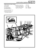
WIRE ROUTING DIAGRAM
ENGINE SWITCH AND OIL WARNING UNIT
1
Oil warning light
2
Wire harness protector
3
Oil warning unit lead (ground)
4
Oil warning unit
5
Clamp
6
TCI unit lead
7
Oil warning unit lead
8
Oil level switch lead
9
Engine switch
A
Pass through the leads to the
wire harness protector, and
then push into the oil warning
unit towards back.
B
Make sure that the gap
between the end of the wire
harness protector and end of
the fuel tank stay is 5 mm (0.2
in) or more.
C
Fasten the ground terminal
and oil warning unit together.
D
Pass the TCI unit lead through
hole in the crankcase.
E
Fasten the connecter area
using the clamp.
Color code
B .........Black
Gy .......Gray
L..........Blue
R .........Red
Y .........Yellow
W/B .....White/Black