background image

4-2

SPEC

GENERAL SPECIFICATIONS

Model name:

MZ250

MZ300

Model code number:

7KBJ

7KBN 

7VBJ

7VBN

Electrical:
  Ignition system

TCI

  Ignition timing (3600 r/min)

BTDC 20° ± 3°

  Spark plug type

BPR4ES (NGK)

  Spark plug gap 


mm (in)

0.7–0.8 (0.028–0.031)

*  The power rating of the engine indicated in the SPECIFICATIONS is the net power output tested 

on an engine model and measured at 3600 r/min.

  Actual power output for an installed engine will vary depending on numerous factors, including 

the operating speed of the engine, environmental conditions, and other variables.

4

Summary of Contents for MZ250 2012

Page 1: ...MZ250 MZ300 SUPPLEMENTARY SERVICE MANUAL 7VB F8197 11 LIT 19616 01 88 cover indd 1 2012 10 30 18 14 10 ...

Page 2: ...cover indd 2 2012 10 30 18 14 11 ...

Page 3: ...ations and significant changes in specifications or procedures will be forwarded to all Authorized Yamaha dealers and will where applicable appear in future editions of this manual HOW TO USE THIS MANUAL PARTICULARLY IMPORTANT INFORMATION Particularly important information is distin guished in this manual by the following nota tions This is the safety alert symbol It is used to alert you to potent...

Page 4: ...f 1st 2nd 6 5 4 3 1 2 7 8 9 9 7 8 7 Nm 0 7 m kgf 5 1 ft lbf 11 Nm 1 1m kgf 8 0 ft lbf 11 Nm 1 1m kgf 8 0 ft lbf 20 Nm 2 0 m kgf 14 ft lbf 2 3 Nm 0 23m kgf 1 7 ft lbf Order Job Parts to remove Q ty Remarks Removing the cylinder head cover and cylinder head Remove the parts in the order listed below Fuel tank Refer to FUEL TANK CANISTER on 3 5 Muffler Refer to MUFFLER on 3 7 Air filter Refer to AIR ...

Page 5: ...ts Engine Carburetor Electrical Troubleshooting Specifications Filling fluid Lubricant Special tool T R Tightening torque Wear limit clearance Engine speed Electrical data Replace the part with a new one LS Lithium soap base grease M Molybdenum disulfide grease E Engine oil M Molybdenum disulfide oil LT Apply locking agent LOCTITE ...

Page 6: ......

Page 7: ...INDEX GENERAL INFORMATION GEN INFO ENGINE ENG ELECTRICAL ELEC SPECIFICATIONS SPEC 1 2 3 4 ...

Page 8: ...NE GOVERNOR 2 1 MZ250A MZ300A 2 1 MZ250K 2 2 MZ300K 2 3 ADJUSTING THE GOVERNOR 2 4 CHAPTER 3 ELECTRICAL CIRCUIT DIAGRAM 3 1 MZ250 MZ300 3 1 CHAPTER 4 SPECIFICATIONS GENERAL SPECIFICATIONS 4 1 MAINTENANCE SPECIFICATIONS 4 3 ENGINE 4 3 ELECTRICAL 4 7 TIGHTENING TORQUES 4 8 GENERAL TORQUE SPECIFICATIONS 4 10 LUBRICATION POINTS AND TYPE OF LUBRICANTS 4 11 WIRE ROUTING DIAGRAM 4 12 UPPER SIDE VIEW 4 12...

Page 9: ...e as shown in the illustration TIP The first three digits identify the model and the remaining digits indicates the production number STARTING SERIAL NUMBER Model Code Starting serial number MZ250AAIA0 7KBJ 7KBJ 1000101 MZ250KHID0 7KBN 7KBN 1000101 MZ300AAIA0 7VBJ 7VBJ 1000101 MZ300KHID3 7VBN 7VBN 1000101 MZ300KHIDM 7VBN 7VBN 2000101 TIP Designs and specifications are subject to change without not...

Page 10: ...040 45 45 1 6 5 1 12 7 110 0 054 0 4 M8 1 25 DEPTH18 4 3 8 16UNC2B DEPTH18 4 5 4 5 MZ300 AAIA0 7VBJ MZ250 KHID0 7KBN 94 5 110 0 054 0 22 161 0 021 0 25 4 0 021 0 146 08 0 040 0 18 46 8 58 7 4 5 5 29 5 76 5 16 24UNF 2B 3 16 å 4 M8 1 25 DEPTH18 4 12 7 146 08 1 6 5 1 30 30 4 5 0 0 040 4 5 45 45 3 8 16UNC2B DEPTH18 110 0 054 0 MZ300 KHID3 7VBN MZ300 KHIDM 7VBN 1 UNF Unified fine thread Unit in 2 UNC U...

Page 11: ...1 3 GEN INFO DIMENSIONS TOP MZ250A MZ300A Unit in mm LEFT SIDE MZ250A MZ300A Unit in mm 1 38 35 1 38 35 4 M8 0 05 1 25 DEPTH 0 71 18 4 06 103 16 77 426 ...

Page 12: ...1 4 GEN INFO DIMENSIONS RIGHT SIDE MZ250A MZ300A Unit in mm 5 26 133 5 18 27 464 4 13 105 3 56 90 5 ...

Page 13: ...MZ300A Unit in mm cm3 ON OFF 15 24 387 7 20 183 3 50 89 0 83 21 2 26 57 5 2 32 59 1 46 37 2 0 43 11 1 06 27 SLOT HOLE 2 0 43 11 HOLE MOUNTING BASE MZ250A MZ300A Unit in mm 2 0 43 11 4 13 105 3 56 90 5 2 0 43 11 2 32 59 1 46 37 4 R 0 63 16 ...

Page 14: ...EN INFO DIMENSIONS TOP MZ250K MZ300K Unit in mm LEFT SIDE MZ250K MZ300K Unit in mm 10 91 277 5 75 146 1 38 35 1 38 35 4 M8 0 05 1 25 DEPTH 0 71 18 5 61 142 5 7 09 180 10 63 270 7 09 180 2 4 06 103 15 91 404 ...

Page 15: ...1 7 GEN INFO DIMENSIONS RIGHT SIDE MZ250K MZ300K Unit in mm 5 26 133 5 6 34 161 ...

Page 16: ...Z300K Unit in mm cm3 ON OFF 15 91 404 7 87 200 4 15 105 5 0 83 21 2 26 57 5 2 32 59 1 46 37 2 0 43 11 1 06 27 SLOT HOLE 2 0 43 11 HOLE MOUNTING BASE MZ250K MZ300K Unit in mm 2 0 43 11 4 13 105 3 56 90 5 2 0 43 11 2 32 59 1 46 37 4 R 0 63 16 ...

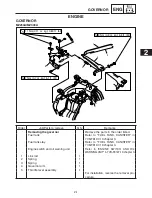
Page 17: ...isted Fuel tank Refer to FUEL TANK CANISTER in 7VB F8197 10 chapter 3 Fuel tank stay Refer to FUEL TANK CANISTER in 7VB F8197 10 chapter 3 Engine switch and oil warning unit Refer to ENGINE SWITCH AND OIL WARNING UNIT in 7VB F8197 10 chapter 3 1 Link rod 1 2 Spring 1 3 Spring 1 4 Governor arm 1 5 Throttle lever assembly 1 For installation reverse the removal pro cedure ENGINE GOVERNOR MZ250A MZ300...

Page 18: ...y Remarks Removing the governor Remove the parts in the order listed Engine switch and oil warning unit Refer to ENGINE SWITCH AND OIL WARNING UNIT in 7VB F8197 10 chapter 3 1 Link rod 1 2 Spring 1 3 Spring 1 4 Governor arm 1 5 Adjusting plate assembly 1 For installation reverse the removal pro cedure MZ250K ...

Page 19: ...to remove Q ty Remarks Removing the governor Remove the parts in the order listed Engine switch and oil warning unit Refer to ENGINE SWITCH AND OIL WARNING UNIT in 7VB F8197 10 chapter 3 1 Link rod 1 2 Spring 1 3 Spring 1 4 Governor arm 1 5 Adjusting plate assembly 1 For installation reverse the removal pro cedure MZ300K ...

Page 20: ...FUEL TANK CANISTER in 7VB F8197 10 chapter 3 2 Adjust 9 Governor Adjustment steps a Loosen the governor arm bolt 1 b Turn the governor arm 2 clockwise until it stops c Turn the governor shaft 3 clockwise until it stops d Tighten the governor arm bolt 1 8 Nm 0 8 m kgf 5 8 ft lbf ...

Page 21: ... B B B W B W B W Y Y R R 1 2 3 4 5 6 1 Spark plug 2 TCI unit 3 Oil warning unit 4 Oil level switch 5 Oil warning light 6 Engine switch Color code B Black L Blue R Red Y Yellow B W Black White ELECTRICAL CIRCUIT DIAGRAM MZ250 MZ300 3 ...

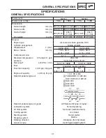
Page 22: ...3 15 2 32 Compression ratio 8 7 1 8 4 1 Standard compression kPa kg cm2 psi pressure 450 550 4 50 5 50 65 25 79 75 Net output kW PS r min 5 4 7 3 3600 7 0 9 5 3600 Fuel Unleaded regular gasoline Fuel tank capacity L US gal Imp gal 5 5 1 45 1 21 5 5 1 45 1 21 Engine oil quantity L US qt Imp qt 1 0 1 06 0 88 Recommended engine oil A YAMALUBE 4 10W 40 SAE 10W 30 or 10W 40 B SAE 30 C SAE 20 D SAE 10W ...

Page 23: ... type BPR4ES NGK Spark plug gap mm in 0 7 0 8 0 028 0 031 The power rating of the engine indicated in the SPECIFICATIONS is the net power output tested on an engine model and measured at 3600 r min Actual power output for an installed engine will vary depending on numerous factors including the operating speed of the engine environmental conditions and other variables 4 ...

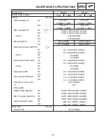
Page 24: ... Piston pin diameter 18 995 19 000 0 7478 0 7480 Limit 18 975 0 7470 Piston ring mm in Top ring Type Barrel Dimensions B T 1 2 2 8 0 0472 0 1102 1 2 2 9 0 0472 0 1142 End gap 0 15 0 30 0 0059 0 0118 0 20 0 35 0 0079 0 0138 Limit 0 55 0 0217 0 6 0 0236 Side clearance 0 04 0 08 0 0016 0 0031 Limit 0 13 0 0051 2nd ring Type Taper Dimensions B T 1 2 3 0 0 0472 0 1181 1 2 3 2 0 0472 0 1260 End gap 0 15...

Page 25: ...mall end diameter A 19 006 19 020 0 7483 0 7488 Oil clearance 0 006 0 025 0 0002 0 0010 Big end diameter B 34 000 34 015 1 3386 1 3392 Big end oil clearance 0 016 0 046 0 0006 0 0018 Limit 0 09 0 0035 Camshaft mm in Camshaft outside diameter Camshaft lobe dimensions 32 50 32 60 1 280 1 284 32 10 32 20 1 264 1 268 A IN Limit 32 30 1 272 31 90 1 256 A EX 32 07 32 17 1 263 1 267 32 50 32 60 1 280 1 2...

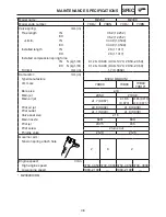
Page 26: ... 0276 0 0354 EX 0 7 0 9 0 0276 0 0354 Limit IN 1 6 0 063 EX 1 6 0 063 Valve seat contact width IN 0 7 0 9 0 0276 0 0354 EX 0 7 0 9 0 0276 0 0354 Limit IN 1 6 0 063 EX 1 6 0 063 Valve seat width IN 0 7 0 9 0 0276 0 0354 EX 0 7 0 9 0 0276 0 0354 Valve margin thickness IN 1 0 1 4 0 0394 0 0551 EX 1 0 1 4 0 0394 0 0551 Valve stem runout limit 0 01 0 0004 θ 90 Valve guide Guide inside diameter IN 6 000...

Page 27: ...669 Carburetor mm in Type manufacture BV24 18 MIKUNI I D mark 7KB00 7VB00 7VB00 7VB10 Bore size ø18 Main jet 96 3 103 8 Main air jet ø1 7 0 067 ø1 85 0 073 ø1 85 0 073 ø1 8 0 071 Pilot air jet ø0 8 0 032 ø1 0 0 039 Pilot outlet ø1 1 0 043 ø1 0 0 039 Valve seat size ø1 5 Main nozzle 62B 60A Pilot jet 37 5 45 Pilot screw 2 turns out Throttle valve 120 125 Governor arm Tension spring attach hole 2 8 ...

Page 28: ...trical Ignition system Ignition timing at 3600 r min BTDC 20 3 Primary coil resistance Ω 20 0 8 Secondary coil resistance kΩ 20 11 7 Spark plug cap resistance kΩ 3 75 6 25 at 20 C 68 F TCI unit air gap mm in 0 4 0 6 0 0157 0 0236 Minimum spark gap mm in 6 0 0 24 Charging coil resistance Green Red Ground Ω 20 1 2 ...

Page 29: ...M18 1 5 120 12 87 Charging coil bolt M6 1 0 7 0 7 5 1 Charging coil clamp bolt M6 1 0 7 0 7 5 1 Governor arm bolt M6 1 0 8 0 8 5 8 Throttle lever assembly bolt M6 1 0 7 0 7 5 1 Throttle lever assembly plate screw M5 0 8 1 1 0 11 0 80 Throttle lever assembly wire bolt M4 0 7 1 1 0 11 0 80 Adjusting plate assembly bolt M6 1 0 7 0 7 5 1 Adjusting plate assembly bolt M8 1 25 16 1 6 12 Oil warning unit...

Page 30: ...oke model 7 0 7 5 1 Carburetor drain screw 1 3 0 13 0 94 Main jet 0 7 0 07 0 52 Pilot jet holder screw 3 5 0 35 2 5 Throttle valve screw 1 0 0 10 0 72 Choke valve screw 0 7 0 07 0 52 Choke lever holder screw 1 3 5 0 35 2 5 Choke lever holder screw 2 2 0 0 20 1 4 Choke solenoid holder screw 3 5 0 35 2 5 Choke solenoid bracket assembly screw 1 5 0 5 3 6 Choke solenoid bracket assembly screw 2 2 0 0 ...

Page 31: ...included in the applicable sections of this book To avoid warpage tight en multi fastener assemblies in a crisscross fashion in progressive stages until full torque is reached Unless otherwise specifications call for clean dry treads Components should be at room temperature Tread size Tightening torque Nm m kgf ft lbf M4 2 0 2 1 5 M5 3 0 3 2 2 M6 7 0 7 5 2 M7 10 1 0 7 4 M8 15 1 5 11 1 M10 30 3 0 2...

Page 32: ...ting rod big end E Crank pin E Crankshaft journal Connecting rod cap bolt E Piston pin E Piston E Crankshaft gear teeth E Valve stem E Valve stem end Valve rocker arm shaft Valve push rod end E Valve lifter stem E Camshaft lobe E Camshaft gear teeth E Decompressor pin E Camshaft journal E Governor collar internal surface E Governor shaft meet surface E Governor weight moving point E ...

Page 33: ...warning light A Screw in the high tension code until it touches the spark plug cap B Route the TCI unit lead as shown C Pass through the leads to the wire harness protector and then push into the oil warning unit towards back D Make sure that the gap between the end of the wire harness protector and end of the crank case is 5 mm 0 2 in or more E Fasten the ground terminal and engine switch togethe...

Page 34: ...Pass through the leads to the wire harness protector and then push into the oil warning unit towards back B Make sure that the gap between the end of the wire harness protector and end of the fuel tank stay is 5 mm 0 2 in or more C Fasten the ground terminal and oil warning unit together D Pass the TCI unit lead through hole in the crankcase E Fasten the connecter area using the clamp Color code B...

Page 35: ...ARGING COIL 1 High tension code 2 Flywheel 3 Charging coil 4 Clamp 5 TCI unit A Make sure that the high ten sion cord is not pinched when installing the flywheel cover B Adjust the TCI unit air gap between 0 4 0 6 mm 0 0157 0 0236 in on both sides ...

Page 36: ...4 15 SPEC WIRE ROUTING DIAGRAM 1 Clamp 2 Oil level switch A Touch the tube gray with the grommet B Route the oil level switch lead as shown OIL LEVEL SWITCH CRANKCASE COVER ...

Page 37: ...4 16 SPEC WIRE ROUTING DIAGRAM 1 TCI unit lead 2 Oil level switch lead A Route the TCI unit lead as shown Color code Gy Gray UPPER SIDE VIEW MZ250KHID0 MZ300KHID3 ...

Page 38: ...s ground A Route the wire harness under the high tension code B Route the TCI unit lead and wire harness as shown C Install the TCI unit and wire harness into the base of the crank case guide Make sure that the TCI lead is installed above the wire harness Color code B Black Gy Gray B W Black White G R Green Red UPPER SIDE VIEW MZ300KHIDM ...

Page 39: ...Charging coil lead 4 Charging coil A Route the wire harness under the breather hose B Install the clamp as shown C Position the wire harness so that it does not contact with the cylinder head Color code G R Green Red CARBURETOR AND CHARGING COIL MZ300KHIDM ...

Page 40: ...4 19 SPEC ...

Page 41: ...1 2 3 4 5 6 1 Spark plug 2 TCI unit 3 Oil warning unit 4 Oil level switch 5 Oil warning light 6 Engine switch Color code B Black L Blue R Red Y Yellow B W Black White MZ250 MZ300 2012 CIRCUIT DIAGRAM cover indd 3 2012 10 30 18 14 11 ...

Page 42: ...2012_09 1 cover indd 4 2012 10 30 18 14 11 ...

Reviews: