


4-12
SPEC
WIRE ROUTING DIAGRAM
WIRE ROUTING DIAGRAM
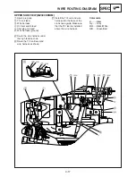
UPPER SIDE VIEW
1
Spark plug cap
2
TCI unit lead
3
Oil level switch lead
4
Oil warning unit
5
Engine switch
6
Engine switch lead (ground)
7
Wire harness protector
8
Oil warning light
A
Screw in the high tension code
until it touches the spark plug
cap.
B
Route the TCI unit lead as
shown.
C
Pass through the leads to the
wire harness protector, and
then push into the oil warning
unit towards back.
D
Make sure that the gap
between the end of the wire
harness protector and end of
the crank case is 5 mm (0.2 in)
or more.
E
Fasten the ground terminal
and engine switch together.
Color code
Gy .......Gray