(3-3) REGISTERED PARAMETER NUMBER
STATUS
1011nnnn(BnH)
n = 0 – 15 CHANNEL NUMBER
LSB
01100100(64H)
RPN LSB
0ppppppp
p = RPN LSB (Refer to the table as shown below.)
MSB
01100101(65H)
RPN MSB
0qqqqqqq
q = RPN MSB (Refer to the table as shown below.)
DATA ENTRY MSB
00000110(06H)
DATA VALUE
0mmmmmmm
m = Data Value
DATA ENTRY LSB
00100110(26H)
DATA VALUE
0lllllll
l = Data Value
First, designate the parameter using RPN MSB/LSB numbers. Then, set its value with data entry MSB/LSB.
RPN
D.ENTRY
LSB MSB
MSB LSB
PARAMETER NAME
DATA RANGE
00H 00H
mmH ---
PITCH BEND SENSITIVITY
00H - 18H (0 - 24 semitones)
01H 00H
mmH llH
MASTER FINE TUNE
{mmH,llH}={00H,00H}-{40H,00H}-{7FH,7FH}
(-8192*100/8192) - 0 - (+8192*100/8192)
02H 00H
mmH ---
MASTER COARSE TUNE
28H - 40H - 58H (-24 - 0 - +24 semitones)
7FH 7FH
--- ---
RPN RESET
RPN numbers will be left not designated.
The internal values are not affected.
(3-4) NON-REGISTERED PARAMETER NUMBER
There are no applicable parameters.
These are transmitted to the Plug-in board.
(3-5) SYSTEM REAL TIME MESSAGES
(3-5-1) ACTIVE SENSING
STATUS
11111110(FEH)
Transmitted at every 200 msec.
Once this code is received, the instrument starts sensing. When no status nor data is received for over
approximately 350 ms, MIDI receiving buffer will be cleared, and the sounds currently played is forcibly turned off.
(3-6) SYSTEM EXCLUSIVE MESSAGE
(3-6-1) UNIVERSAL NON REALTIME MESSAGE
(3-6-1-1) GENERAL MIDI MODE ON
F0H 7EH 7FH 09H 01H F7H
The PLG100-XG Plug-in board installed to the instrument, will receive this message when the instrument is in the
Song/Pattern mode and SYSTEM Receive GM/XG is set to on. The Part values will be reset according to the
SYSTEM Internal Part settings.
The internal tone generator block will receive this message when the instrument is in the Song/Pattern mode.
(3-6-1-2) IDENTITY REQUEST (Receive only)
F0H 7EH 0nH 06H 01H F7H
(“n” = Device No. However, this instrument receives under “omni.”)
(3-6-1-3) IDENTITY REPLY (Transmit only)
F0H 7EH 7FH 06H 02H 43H 00H 41H ddH ddH 00H 00H 00H 7FH F7H
dd; Device Number Code
MOTIF ES6: 69 05
MOTIF ES7: 6A 05
MOTIF ES8: 6B 05
(3-6-2) UNIVERSAL REALTIME MESSAGE
(3-6-2-1) MIDI MASTER VOLUME
F0H 7FH 7FH 04H 01H llH mmH F7H
Sets the MASTER VOLUME value.
The value “mm” is used to set the master volume (the value “ll” should be ignored).
(3-6-3) PARAMETER CHANGE
(3-6-3-1) XG SYSTEM ON
11110000
F0
Exclusive Status
01000011
43
YAMAHA ID
0001nnnn
1n
Device Number
01001100
4C
Model ID
0aaaaaaa
0
Address High
0aaaaaaa
0
Address Mid
0aaaaaaa
7E
Address Low
0
0
Data
11110111
F7
End of Exclusive
The PLG100-XG Plug-in board installed to the instrument, will receive this message when the instrument is in the
Song/Pattern mode and SYSTEM Receive GM/XG is set to on. The Part values will be reset according to the
SYSTEM Internal Part settings.
The internal tone generator block will not receive this message.
Be aware that executing this message takes about 170 ms, and that an appropriate interval must be allowed before
executing the subsequent message.
(3-6-3-2) NATIVE PARAMETER CHANGE, MODE CHANGE
11110000
F0
Exclusive Status
01000011
43
YAMAHA ID
0001nnnn
1n
Device Number
01111111
7F
Model ID
00000000
00
Model ID
0aaaaaaa
aaaaaaa
Address High
0aaaaaaa
aaaaaaa
Address Mid
0aaaaaaa
aaaaaaa
Address Low
0ddddddd
ddddddd
Data
|
|
11110111
F7
End of Exclusive
For parameters with data size of 2 or more, the appropriate number of data bytes will be transmitted.
See the following MIDI Data Table for Address and Byte Count.
(3-6-4) BULK DUMP
11110000
F0
Exclusive Status
01000011
43
YAMAHA ID
0000nnnn
0n
Device Number
01111111
7F
Model ID
00000000
00
Model ID
0bbbbbbb
bbbbbbb
Byte Count
0bbbbbbb
bbbbbbb
Byte Count
0aaaaaaa
aaaaaaa
Address High
0aaaaaaa
aaaaaaa
Address Mid
0aaaaaaa
aaaaaaa
Address Low
0
0
Data
|
|
0ccccccc
ccccccc
Check-sum
11110111
F7
End of Exclusive
See the following BULK DUMP Table for Address and Byte Count.
The Check sum is the value that results in a value of 0 for the lower 7 bits when the Byte Count, Start Address, Data
and Check sum itself are added.
(3-6-5) DUMP REQUEST
11110000
F0
Exclusive Status
01000011
43
YAMAHA ID
0010nnnn
2n
Device Number
01111111
7F
Model ID
00000000
00
Model ID
0aaaaaaa
aaaaaaa
Address High
0aaaaaaa
aaaaaaa
Address Mid
0aaaaaaa
aaaaaaa
Address Low
11110111
F7
End of Exclusive
See the following DUMP REQUEST Table for Address and Byte Count.
(3-6-6) PARAMETER REQUEST
11110000
F0
Exclusive Status
01000011
43
YAMAHA ID
0011nnnn
3n
Device Number
01111111
7F
Model ID
00000000
00
Model ID
0aaaaaaa
aaaaaaa
Address High
0aaaaaaa
aaaaaaa
Address Mid
0aaaaaaa
aaaaaaa
Address Low
11110111
F7
End of Exclusive
See the following MIDI Data Table for Address.
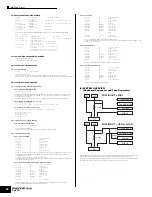
(4) SYSTEM OVERVIEW
(Keyboard, Sequencer and Tone Generator)
Although three types of note on/note off data, received via MIDI, played by the internal sequencer and played on the
keyboard will be distinguished, the other controllers (channel messages) equally affect the entire notes.
ALL SOUND OFF clears all the sounds in the specific channel(s) played by both the keyboard and the data via MIDI.
ALL NOTES OFF received via MIDI clears the sounds in the specific channel(s) played via MIDI.
SEQ
KBD
TG
MIDI In
MIDI Out
From USB/mLAN
To USB/mLAN
Local Sw
MIDI IN/OUT = MIDI
SEQ
KBD
TG
Local Sw
Thru Port
MIDI IN/OUT = USB or mLAN
MIDI In
MIDI Out
From USB/mLAN
To USB/mLAN
66
Data List
MIDI Data Format

