


5-15
E
POWR
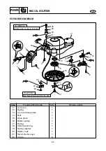
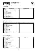
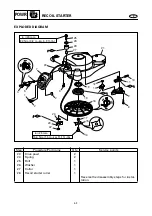
ELECTRICAL UNIT
EXPLODED DIAGRAM
Step
Procedure/Part name
Q’ty
Service points
4
Ignition coil
1
5
Spark plug lead
2
6
Rectifier/regulator
(EH, EHT, E, ET)
1
7
Ground lead
2
8
Pulser coil
1
9
Engine temperature sensor
1
10
Oil pressure switch connector
1
11
Oil pressure switch
1
NOTE:
The aluminum side of the rectifier/regula-
tor must face the engine.
Summary of Contents for F25A
Page 422: ...E TRBL ANLS CHAPTER 9 TROUBLE ANALYSIS TROUBLE ANALYSIS 9 1 TROUBLE ANALYSIS CHART 9 1 ...
Page 442: ......
Page 443: ......


