


DVD-S795/S705
2 - 18
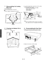
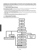
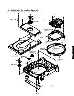
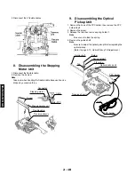
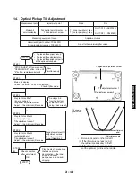
3.
Video Component Signal (CB) Output Adjustment
Do this adjustment after replacing a C.B.A.
Measurement point
Adjustment point
Mode
Disc
Video output terminal
(Y) (CB) Output terminal
VR3201(mother C.B.A.)
Color bar 75%
PLAY (Title 46): DVDT-S15
PLAY (Title 10): DVDT-S01
Measuring equipment, tools
Adjustment value
Screwdriver, Oscilloscope
100mV/div, 10 sc/div
525mVp-p
±
11mV (B, A, G Models)
486mVp-p–10mV (U, C Models)
DVDT-S15 (AX07320)
or
DVDT-S01 (TX946080)
Purpose: To maintain video signal output compatibility.
1. Connect the oscilloscope to the video output terminal and terminate at 75 ohms.
2. Apply the trigger at the Y output terminal signal.
3. Adjust VR3201 so that the video component signal (CB) level becomes 525 mVp-p
–
11 mV. (B, A, G Models)/486mVp-p
–
10mV(U, C Models)
Screw
driver
VR3201
486mV
–
10mV
For B, A, G Models
For U, C Models
Summary of Contents for DVD-S705
Page 7: ...DVD S795 S705 1 5 REAR PANELS U C models DVD S795 S705 B G models G model Gold A model ...
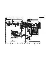
Page 39: ...3 3 3 4 BLOCK DIAGRAM 1 OVERALL BLOCK DIAGRAM ...
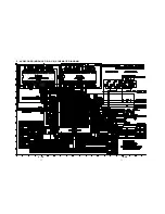
Page 40: ...3 5 2 SERVO BLOCK DIAGRAM 3 6 ...
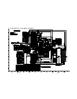
Page 41: ...3 7 3 VIDEO BLOCK DIAGRAM 3 8 ...
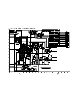
Page 42: ...3 9 4 AUDIO BLOCK DIAGRAM 3 10 ...
Page 60: ...9 0 0 0 0 0 8 9 0 0 3 45 18 FRONT SW HEAD PHONE POWER SW SCHEMATIC DIAGRAM 3 46 ...