


DVD-S795/S705
2 - 9
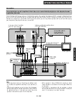
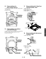
Screw
Intermediate chassis
Traverse unit
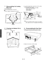
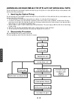
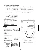
6.
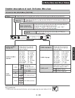
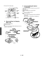
Disassembling the Clamper
Weight, Clamper Yoke, Magnet
and Clamper
1. Remove the 2 screws.
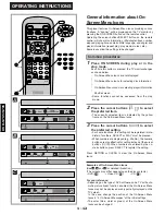
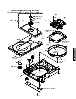
5.
Disassembling the Clamp Base Unit
2. Release the 3 tabs on the clamper.
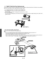
Note
Be sure to take static electricity counterneasures before
disconnecting the flexible cable. (Refer to page 2-8,
Static Electricity Countermeasures.)
1. Remove the tab, and pull out the clamper.
7.
Disassembling the Traverse
Unit
1. Remove the 3 screws.
Clamp base unit
Loading base
Screw
Screw
Stopper
Tab
Clamper unit
Clamper base
Tab
3-clamper tabs
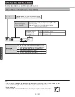
Yoke
Magnet
Clamper yoke
Screw
Magnet
Clamper weight
Clamper
Clamper base
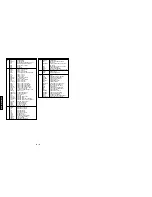
Summary of Contents for DVD-S705
Page 7: ...DVD S795 S705 1 5 REAR PANELS U C models DVD S795 S705 B G models G model Gold A model ...
Page 39: ...3 3 3 4 BLOCK DIAGRAM 1 OVERALL BLOCK DIAGRAM ...
Page 40: ...3 5 2 SERVO BLOCK DIAGRAM 3 6 ...
Page 41: ...3 7 3 VIDEO BLOCK DIAGRAM 3 8 ...
Page 42: ...3 9 4 AUDIO BLOCK DIAGRAM 3 10 ...
Page 60: ...9 0 0 0 0 0 8 9 0 0 3 45 18 FRONT SW HEAD PHONE POWER SW SCHEMATIC DIAGRAM 3 46 ...