


DVD-S795/S705
2 - 8
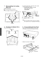
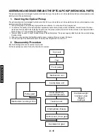
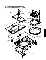
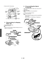
4.
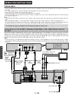
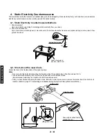
Static Electricity Countermeasures
The laser diode inside the traverse unit (optical pickup) can be damaged by static electricity from your body. Be sure to take static
electricity countermeasures when working around the optical pickup.
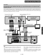
1. Ground yourself
Use an anti-static wrist strap to discharge static electricity from your body.
2. Ground the workbench
Lay a conductive meterial (sheet) or steel sheet on the surface where the traverse unit (optical pickup) is to be placed, then
ground the sheet.
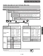
4-1. Static Electricity Countermeasure Methods
Solder the land in the flexible cable of the optical pickup.
Notes
•
Be sure to do this befer disconnecting the flexible cable of the optical pickup from the module C.B.A.
•
Use an anti-static soldering iron to short-circuit and unshort-circuit laser diode.
(Recommended soldering iron: Hakko with ESD countermeasure)
•
After you have finished repairing the laser diode, follow the correct procedure to remove the solder from the short-circuit
location. (Refer to page 2-7, Assembling and Disassembling the Optical Pickup (Mechanical Parts).)
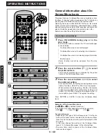
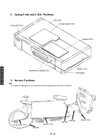
4-2. Short-circuit the laser diode
Anti-static wrist strip
1M
Conductive material
(sheet) or steel sheet
Use a clip or other item to
ground the unit.
Flexible cable
Pickup unit
Solder
(Magnified view)
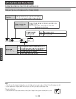
Summary of Contents for DVD-S705
Page 7: ...DVD S795 S705 1 5 REAR PANELS U C models DVD S795 S705 B G models G model Gold A model ...
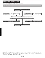
Page 39: ...3 3 3 4 BLOCK DIAGRAM 1 OVERALL BLOCK DIAGRAM ...
Page 40: ...3 5 2 SERVO BLOCK DIAGRAM 3 6 ...
Page 41: ...3 7 3 VIDEO BLOCK DIAGRAM 3 8 ...
Page 42: ...3 9 4 AUDIO BLOCK DIAGRAM 3 10 ...
Page 60: ...9 0 0 0 0 0 8 9 0 0 3 45 18 FRONT SW HEAD PHONE POWER SW SCHEMATIC DIAGRAM 3 46 ...