


FUEL INJECTION SYSTEM
8-38
EAS27362
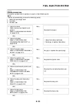
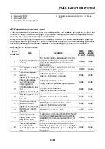
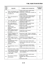
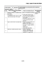
SELF-DIAGNOSTIC FUNCTION TABLE
If the ECU detects an abnormal signal from a sensor while the vehicle is being driven, the ECU illu-
minates the engine trouble warning light and provides the engine with alternate operating instruc-
tions that are appropriate for the type of malfunction.
When an abnormal signal is received from a sensor, the ECU processes the specified values that
are programmed for each sensor in order to provide the engine with alternate operating instructions
that enable the engine to continue to operate or stop operating, depending on the conditions.
Self-Diagnostic Function table
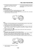
a. Main switch “OFF”
b. Main switch “ON”
c. Engine trouble warning light off
d. Engine trouble warning light on for 1.4 sec-
onds
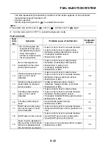
Fault
code No.
Item
Symptom
Able/
unable
to start
Able/
unable
to drive
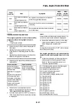
11
Cylinder identification
sensor
No normal signals are received from the
cylinder identification sensor when the
engine is started or while the vehicle is
being driven.
Unable
Able
12
Crankshaft position
sensor
No normal signals are received from the
crankshaft position sensor.
Unable
Unable
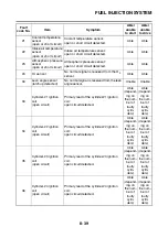
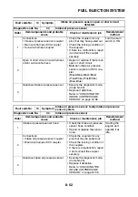
13
Intake air pressure
sensor
(open or short circuit)
Intake air pressure sensor:
open or short circuit detected.
Able
Able
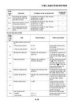
14
Intake air pressure
sensor hose line
(piping system)
Intake air pressure sensor:
faulty intake air pressure sensor system.
Able
Able
15
Throttle position sen-
sor
(open or short circuit)
Throttle position sensor:
open or short circuit detected.
Able
Able
16
Throttle position sen-
sor
(stuck)
Throttle position sensor is stuck.
Able
Able
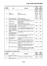
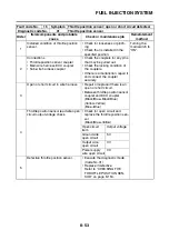
17
EXUP servo motor
potention circuit
(open or short circuit)
EXUP servo motor potention circuit:
open or short circuit detected.
Able
Able
18
EXUP servo motor
(stuck)
EXUP servo motor is stuck.
Able
Able
19
Sidestand switch
(open circuit in the
wire to the ECU)
Open circuit in the input line of ECU No.24
terminal is detected when start switch is
pressed from the sidestand switch to the
ECU.
Unable
Unable
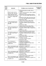
20
Intake air pressure
sensor or atmo-
spheric pressure sen-
sor
When the main switch is turned to “ON”,
the atmospheric pressure sensor voltage
and intake air pressure sensor voltage dif-
fer greatly.
Able
Able
Summary of Contents for 2008 Fazer FZ1-N
Page 1: ...SERVICE MANUAL FZ1 N X FZ1 S X FZ1 SA FZ1 NA 2008 5D0 28197 E1 ...
Page 6: ......
Page 8: ......
Page 44: ...SPECIAL TOOLS 1 35 ...
Page 63: ...TIGHTENING TORQUES 2 18 ...
Page 69: ...LUBRICATION POINTS AND LUBRICANT TYPES 2 24 ...
Page 72: ...LUBRICATION SYSTEM CHART AND DIAGRAMS 2 27 EAS20410 LUBRICATION DIAGRAMS ...
Page 74: ...LUBRICATION SYSTEM CHART AND DIAGRAMS 2 29 ...
Page 76: ...LUBRICATION SYSTEM CHART AND DIAGRAMS 2 31 ...
Page 78: ...LUBRICATION SYSTEM CHART AND DIAGRAMS 2 33 ...
Page 79: ...LUBRICATION SYSTEM CHART AND DIAGRAMS 2 34 1 Main axle 2 Oil delivery pipe 3 Drive axle ...
Page 80: ...LUBRICATION SYSTEM CHART AND DIAGRAMS 2 35 ...
Page 81: ...LUBRICATION SYSTEM CHART AND DIAGRAMS 2 36 1 Cylinder head 2 Crankshaft ...
Page 82: ...COOLING SYSTEM DIAGRAMS 2 37 EAS20420 COOLING SYSTEM DIAGRAMS ...
Page 83: ...COOLING SYSTEM DIAGRAMS 2 38 1 Water pump 2 Radiator 3 Radiator fan ...
Page 84: ...COOLING SYSTEM DIAGRAMS 2 39 ...
Page 85: ...COOLING SYSTEM DIAGRAMS 2 40 1 Radiator cap 2 Radiator 3 Oil cooler 4 Thermostat ...
Page 86: ...CABLE ROUTING 2 41 EAS20430 CABLE ROUTING ...
Page 88: ...CABLE ROUTING 2 43 MM NN OO FZ1 S X H M M N N O H O FZ1 N X FZ1 S X ...
Page 90: ...CABLE ROUTING 2 45 ...
Page 92: ...CABLE ROUTING 2 47 ...
Page 96: ...CABLE ROUTING 2 51 ...
Page 98: ...CABLE ROUTING 2 53 ...
Page 100: ...CABLE ROUTING 2 55 ...
Page 106: ...CABLE ROUTING 2 61 ...
Page 108: ...CABLE ROUTING 2 63 ...
Page 114: ...CABLE ROUTING 2 69 EE E E F F FF AA A A FZ1 S X ...
Page 116: ...CABLE ROUTING 2 71 ...
Page 118: ...CABLE ROUTING 2 73 ...
Page 121: ......
Page 159: ...ELECTRICAL SYSTEM 3 38 A FZ1 N X FZ1 NA B FZ1 S X FZ1 SA ...
Page 160: ...ELECTRICAL SYSTEM 3 39 ...
Page 163: ......
Page 249: ...INSTALLING THE TRANSMISSION 5 88 ...
Page 366: ...AIR INDUCTION SYSTEM 7 15 ...
Page 370: ...IGNITION SYSTEM 8 1 EAS27090 IGNITION SYSTEM EAS27110 CIRCUIT DIAGRAM ...
Page 374: ...ELECTRIC STARTING SYSTEM 8 5 EAS27160 ELECTRIC STARTING SYSTEM EAS27170 CIRCUIT DIAGRAM ...
Page 380: ...CHARGING SYSTEM 8 11 EAS27200 CHARGING SYSTEM EAS27210 CIRCUIT DIAGRAM ...
Page 381: ...CHARGING SYSTEM 8 12 2 Rectifier regulator 3 AC magneto 6 Main fuse 7 Battery ...
Page 383: ...CHARGING SYSTEM 8 14 ...
Page 384: ...LIGHTING SYSTEM 8 15 EAS27240 LIGHTING SYSTEM EAS27250 CIRCUIT DIAGRAM FZ1 N X ...
Page 386: ...LIGHTING SYSTEM 8 17 EAS5D01027 CIRCUIT DIAGRAM FZ1 S X ...
Page 390: ...SIGNALING SYSTEM 8 21 EAS27270 SIGNALING SYSTEM EAS27280 CIRCUIT DIAGRAM ...
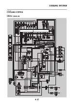
Page 396: ...COOLING SYSTEM 8 27 EAS27300 COOLING SYSTEM EAS27310 CIRCUIT DIAGRAM ...
Page 399: ...COOLING SYSTEM 8 30 ...
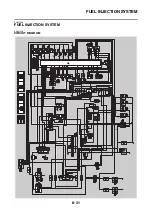
Page 400: ...FUEL INJECTION SYSTEM 8 31 EAS27330 FUEL INJECTION SYSTEM EAS27340 CIRCUIT DIAGRAM ...
Page 443: ...FUEL INJECTION SYSTEM 8 74 ...
Page 444: ...FUEL PUMP SYSTEM 8 75 EAS27550 FUEL PUMP SYSTEM EAS27560 CIRCUIT DIAGRAM ...
Page 447: ...FUEL PUMP SYSTEM 8 78 ...
Page 448: ...IMMOBILIZER SYSTEM 8 79 EAS27640 IMMOBILIZER SYSTEM EAS27650 CIRCUIT DIAGRAM ...
Page 457: ...IMMOBILIZER SYSTEM 8 88 ...
Page 462: ...ABS ANTI LOCK BRAKE SYSTEM 8 93 EAS27740 ABS COMPONENTS CHART FZ1 SA ...
Page 464: ...ABS ANTI LOCK BRAKE SYSTEM 8 95 FZ1 NA ...
Page 466: ...ABS ANTI LOCK BRAKE SYSTEM 8 97 EAS27750 ABS CONNECTOR LOCATION CHART FZ1 SA ...
Page 468: ...ABS ANTI LOCK BRAKE SYSTEM 8 99 FZ1 NA ...
Page 476: ...ABS ANTI LOCK BRAKE SYSTEM 8 107 EAS27810 BASIC PROCESS FOR TROUBLESHOOTING ...
Page 500: ...ELECTRICAL COMPONENTS 8 131 EAS27970 ELECTRICAL COMPONENTS ...
Page 502: ...ELECTRICAL COMPONENTS 8 133 ...
Page 504: ...ELECTRICAL COMPONENTS 8 135 EAS27980 CHECKING THE SWITCHES ...
Page 533: ...TROUBLESHOOTING 9 6 ...
Page 538: ...YAMAHA MOTOR CO LTD 2500 SHINGAI IWATA SHIZUOKA JAPAN ...


