


CRANKSHAFT
5-77
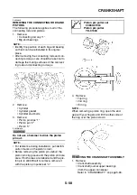
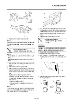
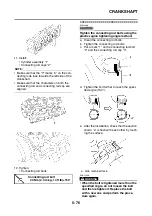
• If they are not flush with each other,
remove the connecting rod bolt and big
end bearing and restart from step “9”. In
this case, make sure to replace the con-
necting rod bolt.
CAUTION:
ECA14680
• Do not use a torque wrench to tighten the
bolt to the specified angle.
• Tighten the bolt until it is at the specified
angles.
▲▲▲▲▲▲▲▲▲▲▲▲▲▲▲▲▲▲▲▲▲▲▲▲▲▲▲▲▲▲
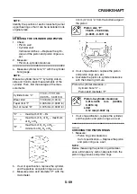
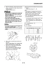
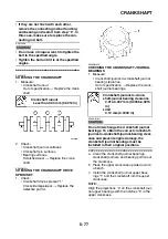
EAS26070
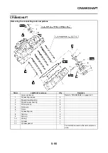
CHECKING THE CRANKSHAFT
1. Measure:
• Crankshaft runout
Out of specification
→
Replace the crank-
shaft.
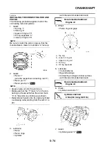
2. Check:
• Crankshaft journal surfaces
• Crankshaft pin surfaces
• Bearing surfaces
Scratches/wear
→
Replace the crank-
shaft.
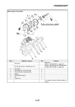
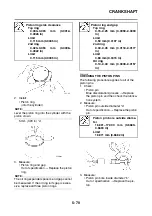
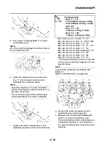
EAS5D01022
CHECKING THE CRANKSHAFT DRIVE
SPROCKET
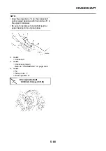
1. Check:
• Crankshaft drive sprocket “1”
Cracks/damage/wear
→
Replace the
defective part(s).
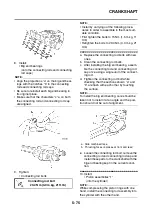
EAS5D01023
CHECKING THE CRANKSHAFT JOURNAL
BEARINGS
1. Measure:
• Crankshaft-journal-to-crankshaft-journal
bearing clearance
Out of specification
→
Replace the crank-
shaft journal bearings.
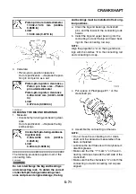
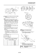
CAUTION:
ECA5D01021
Do not interchange the crankshaft journal
bearings. To obtain the correct crankshaft-
journal-to-crankshaft-journal-bearing clear-
ance and prevent engine damage, the
crankshaft journal bearings must be
installed in their original positions.
▼▼▼▼▼▼▼▼▼▼▼▼▼▼▼▼▼▼▼▼▼▼▼▼▼▼▼▼▼▼
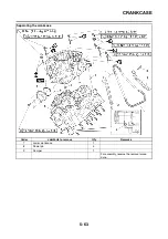
a. Clean the crankshaft journal bearings,
crankshaft journals, and bearing portions of
the crankcase.
b. Place the upper crankcase upside down on
a bench.
c. Install the crankshaft journal upper bear-
ings “1” and the crankshaft into the upper
crankcase.
NOTE:
Align the projections “a” on the crankshaft jour-
nal upper bearings with the notches “b” in the
upper crankcase.
Crankshaft runout
Less than 0.03 mm (0.0012 in)
Crankshaft-journal-to-crank-
shaft-journal bearing clearance
0.014-0.037 mm (0.0006-0.0015
in)
Limit
0.10 mm (0.0039 in)
Summary of Contents for 2008 Fazer FZ1-N
Page 1: ...SERVICE MANUAL FZ1 N X FZ1 S X FZ1 SA FZ1 NA 2008 5D0 28197 E1 ...
Page 6: ......
Page 8: ......
Page 44: ...SPECIAL TOOLS 1 35 ...
Page 63: ...TIGHTENING TORQUES 2 18 ...
Page 69: ...LUBRICATION POINTS AND LUBRICANT TYPES 2 24 ...
Page 72: ...LUBRICATION SYSTEM CHART AND DIAGRAMS 2 27 EAS20410 LUBRICATION DIAGRAMS ...
Page 74: ...LUBRICATION SYSTEM CHART AND DIAGRAMS 2 29 ...
Page 76: ...LUBRICATION SYSTEM CHART AND DIAGRAMS 2 31 ...
Page 78: ...LUBRICATION SYSTEM CHART AND DIAGRAMS 2 33 ...
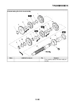
Page 79: ...LUBRICATION SYSTEM CHART AND DIAGRAMS 2 34 1 Main axle 2 Oil delivery pipe 3 Drive axle ...
Page 80: ...LUBRICATION SYSTEM CHART AND DIAGRAMS 2 35 ...
Page 81: ...LUBRICATION SYSTEM CHART AND DIAGRAMS 2 36 1 Cylinder head 2 Crankshaft ...
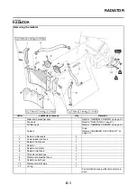
Page 82: ...COOLING SYSTEM DIAGRAMS 2 37 EAS20420 COOLING SYSTEM DIAGRAMS ...
Page 83: ...COOLING SYSTEM DIAGRAMS 2 38 1 Water pump 2 Radiator 3 Radiator fan ...
Page 84: ...COOLING SYSTEM DIAGRAMS 2 39 ...
Page 85: ...COOLING SYSTEM DIAGRAMS 2 40 1 Radiator cap 2 Radiator 3 Oil cooler 4 Thermostat ...
Page 86: ...CABLE ROUTING 2 41 EAS20430 CABLE ROUTING ...
Page 88: ...CABLE ROUTING 2 43 MM NN OO FZ1 S X H M M N N O H O FZ1 N X FZ1 S X ...
Page 90: ...CABLE ROUTING 2 45 ...
Page 92: ...CABLE ROUTING 2 47 ...
Page 96: ...CABLE ROUTING 2 51 ...
Page 98: ...CABLE ROUTING 2 53 ...
Page 100: ...CABLE ROUTING 2 55 ...
Page 106: ...CABLE ROUTING 2 61 ...
Page 108: ...CABLE ROUTING 2 63 ...
Page 114: ...CABLE ROUTING 2 69 EE E E F F FF AA A A FZ1 S X ...
Page 116: ...CABLE ROUTING 2 71 ...
Page 118: ...CABLE ROUTING 2 73 ...
Page 121: ......
Page 159: ...ELECTRICAL SYSTEM 3 38 A FZ1 N X FZ1 NA B FZ1 S X FZ1 SA ...
Page 160: ...ELECTRICAL SYSTEM 3 39 ...
Page 163: ......
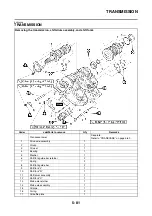
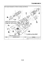
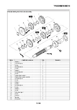
Page 249: ...INSTALLING THE TRANSMISSION 5 88 ...
Page 366: ...AIR INDUCTION SYSTEM 7 15 ...
Page 370: ...IGNITION SYSTEM 8 1 EAS27090 IGNITION SYSTEM EAS27110 CIRCUIT DIAGRAM ...
Page 374: ...ELECTRIC STARTING SYSTEM 8 5 EAS27160 ELECTRIC STARTING SYSTEM EAS27170 CIRCUIT DIAGRAM ...
Page 380: ...CHARGING SYSTEM 8 11 EAS27200 CHARGING SYSTEM EAS27210 CIRCUIT DIAGRAM ...
Page 381: ...CHARGING SYSTEM 8 12 2 Rectifier regulator 3 AC magneto 6 Main fuse 7 Battery ...
Page 383: ...CHARGING SYSTEM 8 14 ...
Page 384: ...LIGHTING SYSTEM 8 15 EAS27240 LIGHTING SYSTEM EAS27250 CIRCUIT DIAGRAM FZ1 N X ...
Page 386: ...LIGHTING SYSTEM 8 17 EAS5D01027 CIRCUIT DIAGRAM FZ1 S X ...
Page 390: ...SIGNALING SYSTEM 8 21 EAS27270 SIGNALING SYSTEM EAS27280 CIRCUIT DIAGRAM ...
Page 396: ...COOLING SYSTEM 8 27 EAS27300 COOLING SYSTEM EAS27310 CIRCUIT DIAGRAM ...
Page 399: ...COOLING SYSTEM 8 30 ...
Page 400: ...FUEL INJECTION SYSTEM 8 31 EAS27330 FUEL INJECTION SYSTEM EAS27340 CIRCUIT DIAGRAM ...
Page 443: ...FUEL INJECTION SYSTEM 8 74 ...
Page 444: ...FUEL PUMP SYSTEM 8 75 EAS27550 FUEL PUMP SYSTEM EAS27560 CIRCUIT DIAGRAM ...
Page 447: ...FUEL PUMP SYSTEM 8 78 ...
Page 448: ...IMMOBILIZER SYSTEM 8 79 EAS27640 IMMOBILIZER SYSTEM EAS27650 CIRCUIT DIAGRAM ...
Page 457: ...IMMOBILIZER SYSTEM 8 88 ...
Page 462: ...ABS ANTI LOCK BRAKE SYSTEM 8 93 EAS27740 ABS COMPONENTS CHART FZ1 SA ...
Page 464: ...ABS ANTI LOCK BRAKE SYSTEM 8 95 FZ1 NA ...
Page 466: ...ABS ANTI LOCK BRAKE SYSTEM 8 97 EAS27750 ABS CONNECTOR LOCATION CHART FZ1 SA ...
Page 468: ...ABS ANTI LOCK BRAKE SYSTEM 8 99 FZ1 NA ...
Page 476: ...ABS ANTI LOCK BRAKE SYSTEM 8 107 EAS27810 BASIC PROCESS FOR TROUBLESHOOTING ...
Page 500: ...ELECTRICAL COMPONENTS 8 131 EAS27970 ELECTRICAL COMPONENTS ...
Page 502: ...ELECTRICAL COMPONENTS 8 133 ...
Page 504: ...ELECTRICAL COMPONENTS 8 135 EAS27980 CHECKING THE SWITCHES ...
Page 533: ...TROUBLESHOOTING 9 6 ...
Page 538: ...YAMAHA MOTOR CO LTD 2500 SHINGAI IWATA SHIZUOKA JAPAN ...


