3
3. Preparations before Operation
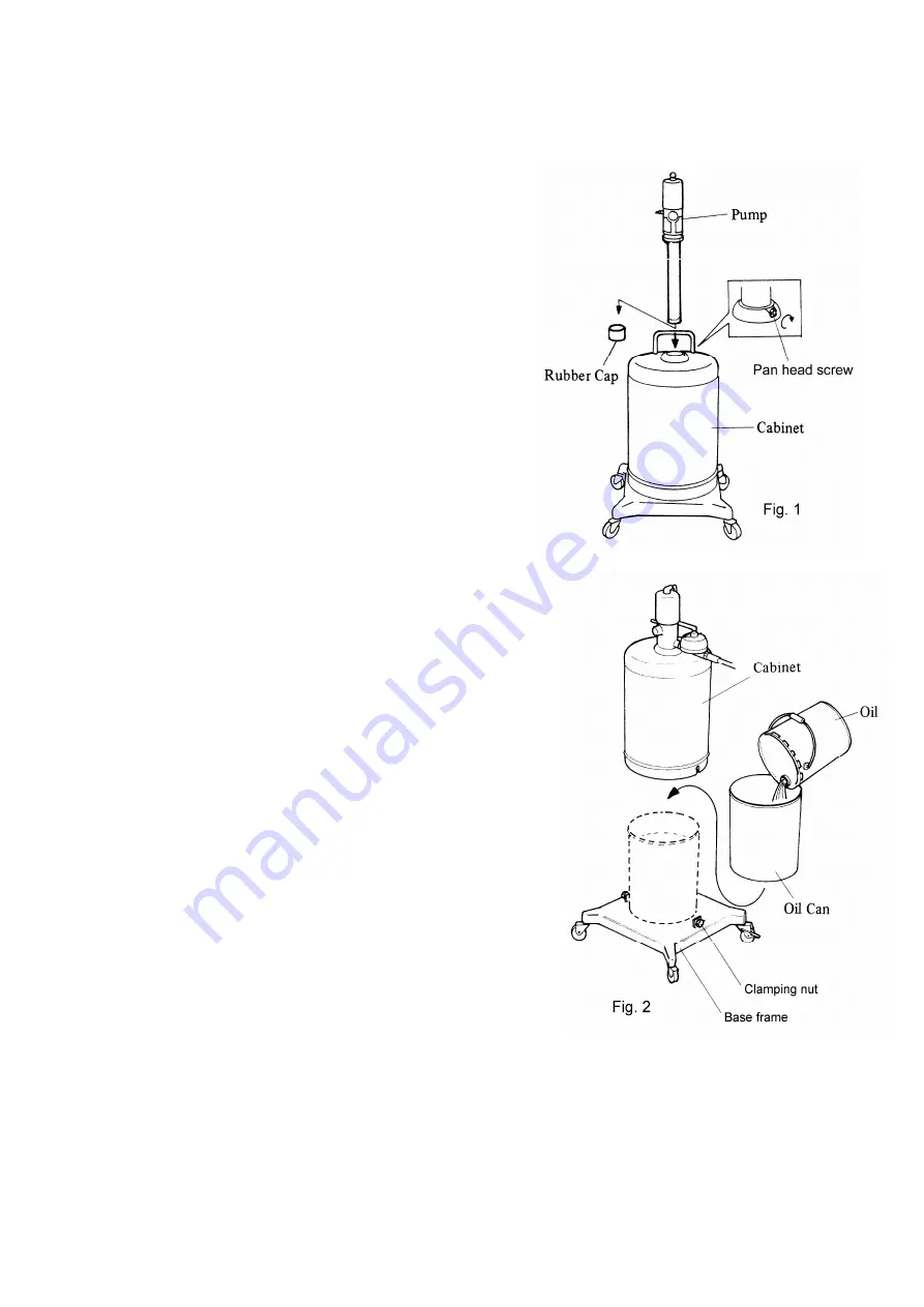
1) First loosen the pan-head screw and take out the pump from
the cabinet.
Remove the rubber cap at the bottom of the pump Ass’y, insert
the pump into the cabinet, and fix it with a pan-head screw.
Refer to <Assembly of Equipment> indicated on the top
surface of the corrugated fiberboard case. (Fig.1)
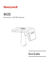
2) Loosen the two clamping nuts at the bottom of the cabinet
(turn them counterclockwise), and remove the cabinet from the
base frame. (Fig.2)
3) Transfer the oil to the exclusive use oil can. (Fig.2)
4) Place a oil can in the middle of the base frame and install the
cabinet as it was. Tighten the clamping nut on both sides
equally. (Fig.2)
5) Install the attached hose and the gun at the oil discharge port
of the pump, and clamp the connecting portion securely.
6) Connect the attached air coupler to the air hose and fix it with
a hose band. (The air hose is separately available.) If the air
coupler to be connected to the compressor is not available,
purchase it separately.
7) When the air coupler is connected to the pump, the pump will
be operated for a while, and the pump and hose will be filled with oil.
After that, the pump operation will stop. If the gun lever is pulled in
this status, the oil lubricator can be used any time.
<Note>
-
Install the air regulator (separately available) at the air supply port
of the pump. The dedicated air regulator is available as the
standard product. Please use it
- Using the air regulator permits adjusting the supply air pressure to
the pump and reducing the wasteful motion of the pump, with the
result that the operability is improved and the pump life is extended.
In the normal operating status, the pointer of the pressure gauge
should be at 0.3 to 0.5 MPa.
Summary of Contents for SGR-55 880267
Page 17: ...MEMO...


