


3
Product and functional description
14
09.2019
ba
-o
.4
.1
.3
-en
-2
.2
-y
3.5
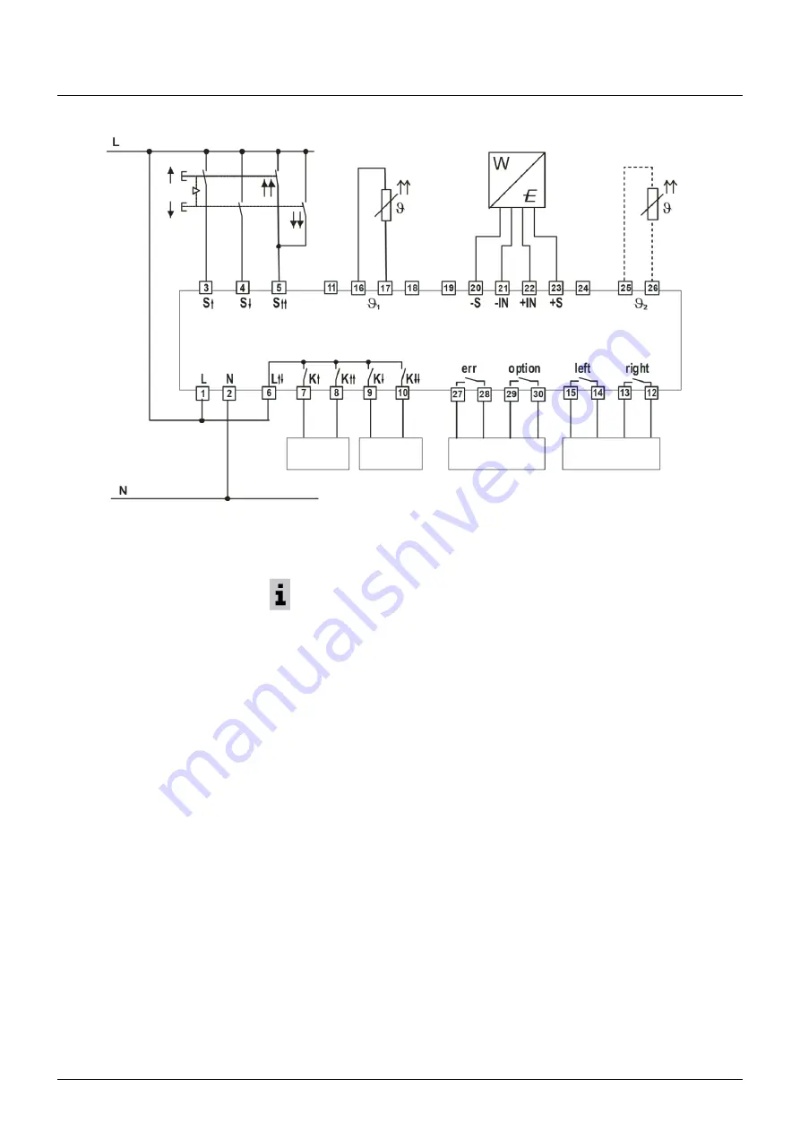
Schematic circuit diagram
3.6
Safety functions
3.6.1
Overload cut-off
The overload cut-off is designed according to Performance Level d, Category 2 in
accordance with ISO 13849-1.
As shown in the schematic circuit diagram, the DMS load sensor is supplied with power
(10 VDC) via the conneS and -S. The load-proportional signal voltage ("load
signal") of the DMS sensor is connected at the conneIN and -IN (mV).
The overload cut-off switches off in the following cases:
•
If the signal voltage between the connections IN+ and IN- exceeds the cut-off thresh-
old setting while
S↑
is active, the
SLE 3
detects "
overload
" and switches the outputs
K↑ and K↑↑
off. The outputs are blocked until no overload is detected any more.
•
If the signal voltage between the connections IN+ and IN- exceeds the cut-off thresh-
old setting while the outputs
K↓
and
K↓↓
are active or when stationary, the
SLE 3
detects "
overload
" after a time of 800 ms and blocks the outputs
K↑
and
K↑↑
until
no overload is detected any more.
As a result of internal filter functions, the maximum response time of the cut-off when
lifting a load from the ground is 500 ms. For the total response time, the elasticity of the
crane system must also be taken into consideration.
"
Overload
" is acknowledged when the load on the hooks drops below 82.5 % of the
maximum lifting capacity and the safety input
S↓
is active for a time of at least 2 seconds.
Switching of the outputs K↓ and K↓↓ is possible when an overload has been
detected!
Op. voltage
LIFT
Op. voltage
LOWER
Op. voltage
SIGNALS
Op. voltage
DRIVE
Load sensor


