Digital Lock Set
Installation Instructions
Handing the Latch Bolt
* Insert a flat blade screwdriver through the back of the lock
case and press on the latch handing screw until the latch bolt
is clear of the face plate.
* Then turn the screw 180 degrees to achieve required handing.
* Fit the lock into the mortice ensuring that the lock face plate is
flush with the edge of the door and screw into place
Fitting the Strike
* Close the door against the door frame and transfer the centre of
the latch bolt onto the jamb.
* Position the strike plate on the door so that it fits against the flat
of the latch bolt
* Close the door and mark the position of the strike plate on the door jamb
* Use the strike plate as a template and mark the inner & outer
edges on the jamb
* Cut a 1mm deep rebate so that the strike is flush with the door jamb
* Drill and chisel out hole to accomodate latch and deadbolt
* Fit strike using only the central screw at first to ensure that it is
positioned correctly
Spindle Length
* Maximum spindle projection on inside of door is 15mm.
* Trim spindle length to suit door thickness.
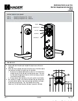
5) Handing and Fitting the Mortice Lock
6) Spindle Length
(HOLE A)
Assembly
(HOLE B)
Interior Handle
Head Cap Screw
Hexagon Socket
BLACK HANDING
SCREWS
4) Handing the Digital Interior Handle Assembly
sure the lever handle is in the horizontal position and the
handle hub aligns with the mortice lock spindle hub.
* Tightening the Hexagon Socket Head Cap Screw making
the spindle hub and rotate the lever handle from right to left.
* Loosen the Hexagon Socket Head Cap Screw located inside
To change factory handing to suit left hand door:
* Remove BLACK handling screw from hole A and relocate
Hole A is for left hand door and Hole B for right hand door.
Handing is for a right hand door with black factory handing
screw located in Hole B.
LEVEL HANDLE
Rotation
it in hole B.
15mm
Max
Digital Lock Set
Installation Instructions
2) Preparing the Door
Viewed from the OUTSIDE
1) Check the Handing of Your Door
(Code Pad Side),your door is
SPECIAL NOTES:
Before commencing installation check that all parts are working correctly.
* Digital Exterior Code Pad Assembly:Enter code C13579, turn handle in both directions.The handle
should turn and return freely under spring pressure.
If you need to change the code you should change and test prior to fitting. - see the Code Change
instructions
right handed if the hinges are
NOTE: ALL UNITS ARE SET
AT THE FACTORY TO SUIT
RIGHT HAND HUNG DOORS.
on the right and your door is
left handed if the hinges are
on the left.
Establish the height that the lock is to be mounted on door and mortice
out for the lock body as detailed on the template.
Fold template and tape to the face of the door aligning the centre line
of latch hub with the mortice lock latch hub.
With the lock body removed, drill mounting screw, cylinder and
escutcheon holes as shown.
NOTE: TO PREVENT DAMAGE TO THE DOOR FACE FROM DRILL
BREAKTHROUGH, MARK BOTH SIDES OF DOOR & DRILL HOLES
HALF WAY THROUGH FROM EACH SIDE
The external key pad handle is fitted with a
clutch to prevent damage from attempted
forced entry. To change the handing first
mount the keypad to the door as per
instruction 6) then apply force to rotate the
handle to the correct handing.
Rotation
3) Handing the Digital Exterior Code
Pad Assembly
HANDLE
HANDLE
OUTSIDE
OUTSIDE
Right Hand
Left Hand
Left Hand
Right Hand
(
LH
)
(
RH
)
(
LH
)
(
RH
)